Search algorithm
- See also

 Availability
 Previous
- Next

-
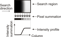
Establishes the intensity profile of the search region.
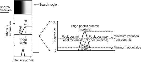
To establish the intensity profile, the algorithm projects the pixels bounded by the two-dimensional search region (or each subregion) into a one-dimensional pixel intensity summation. The algorithm performs the summation according to the search region's origin and the direction of the search, and stores the results in an internal projection buffer. In the following example, each sum represents the intensity of all the pixels in its vertical column.
-
Establishes the edgevalue of each intensity profile value.
The algorithm establishes the edgevalue of each intensity profile value by applying a first derivative filter to the internal projection buffer containing the pixel intensity summation. The filter's output is normalized according to the number of pixels involved in each summation (for a box search region, this corresponds to the box height or width, depending on the search direction) and the maximum pixel value possible for the specified image buffer.
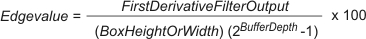
The greater the difference in neighboring intensity profile values, the higher the edgevalue. An edgevalue of 100 represents the most difference, while an edgevalue of 0 represents no difference. The following is an example of a first derivative representation of an intensity profile.
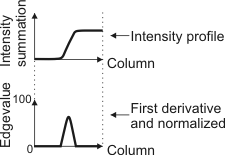
The normalized first derivative of the intensity profile is referred to as the edge profile.
-
Identifies valid edgevalues.
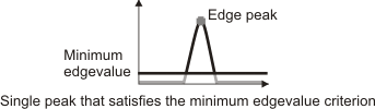
To establish the occurrence of a marker (edge), the algorithm only considers edgevalues above a minimum value, set using MmeasSetMarker() with M_EDGEVALUE_MIN. Given an edge profile, the edgevalue at the summit of the highest peak that satisfies this criterion represents the edge's position.
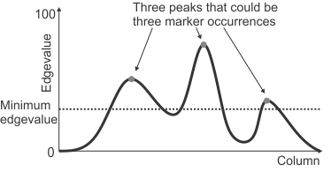
When searching for multiple-occurrence markers, the Measurement module finds the highest peak among those for which the edge profile rises above and then falls below the minimum edgevalue on both sides. By default, only one possible instance of an edge is established from each interval above the specified minimum edgevalue.
When searching for multiple occurrences of edges, some advanced applications might also need you to specify the minimum prominence of the required peaks, using M_EDGEVALUE_VAR_MIN. For more information, see the Minimum variation subsection of this section.
-
Establishes and scores the marker.
Based on the valid edgevalues, the algorithm establishes the marker and gives it a score, in percent. In general, the higher the score, the more confident you can be that the algorithm found the marker you expect. The algorithm rejects any possible marker occurrence that does not meet all the essential characteristics specified using MmeasSetMarker().
By default, the algorithm scores the marker according to its relative strength (maximum edgevalue), as indicated by the default behavior of MmeasSetScore(). This default behavior is usually sufficient and you needn't call this function. If necessary, you can specify characteristics other than strength to affect the score and influence the marker selection process. For example, you can score a marker according to its contrast. Typically, MmeasSetScore() is for advanced applications or when trying to distinguish between similar markers.
-
[-1,1] (M_EULER). This is an FIR filter with a convolution kernel of size 2. This filter is faster but more sensitive to noise, compared to the M_PREWITT filter.
-
[-1,0,1] (M_PREWITT). This is an FIR filter with a convolution kernel of size 3. This filter is slower but less sensitive to noise, compared to the M_EULER filter.
-
An IIR filter (M_SHEN). This is a Shen-Castan Infinite Support Exponential filter. This is an exponential weighting function, of the general form:

This IIR filter is slower than FIR filters (M_EULER or M_PREWITT). However, this filter is less sensitive to noise, can provide more accurate results, and allows you to control the strength of denoising.
To find an edge, stripe, or circle marker in an image, the MIL Measurement module's search algorithm performs the following general steps. Although these steps focus on how MIL establishes an edge marker, they also relate to how MIL establishes stripe and circle markers; fundamentally, MIL uses the same algorithm to establish each edge of a stripe or the edge of a circle.
You can retrieve or draw information about the edge peak or edge profile of the marker by calling MmeasGetResult() or MmeasDraw(). This can be useful, for example, when trying to establish an appropriate minimum edgevalue. For more information, see the Retrieving and drawing edge information subsection of this section.
First derivative filter
As previously discussed, edgevalues are established, in part, by a first derivative filter. You can choose either a Finite Impulse Response (FIR) filter or an Infinite Impulse Response (IIR) filter. Edgevalues can differ depending on which you select.
FIR filters use a non-recursive convolution operation with a predefined kernel of a specified size. To select an FIR filter, use MmeasSetMarker() with M_FILTER_TYPE set to M_EULER or M_PREWITT. Conversely, IIR filters use a recursive convolution operation and have, theoretically, an infinite kernel size. To select an IIR filter, use MmeasSetMarker() with M_FILTER_TYPE set to M_SHEN, and specify the degree of smoothness (strength of denoising) to apply to the internal projection buffer of the search region, using MmeasSetMarker() with M_FILTER_SMOOTHNESS.
Below are the general characteristics of each filter. The default, M_EULER, is typically sufficient for most applications. If necessary, you can try the others to see if they yield better results.
Minimum variation
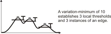
In advanced applications, M_EDGEVALUE_MIN might not give you enough control over identifying the required edges. This can happen when trying to find multiple neighboring edges in the search region, which are formed such that the foreground of the first edge becomes the background of the next edge.
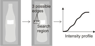
In the search region illustrated above, the pixels transition from gray (somewhat white), to less gray (more white), to white. If you consider the edge profile of the search region (by taking the first derivative and normalizing the intensity profile as previously discussed), you can see that M_EDGEVALUE_MIN does not give you enough control to establish three instances of an edge.
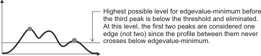
To deal with such cases, you can try using MmeasSetMarker() with M_EDGEVALUE_VAR_MIN to set the minimum required prominence of the peak. To determine if this minimum prominence is met, MIL establishes a local threshold for each peak by subtracting M_EDGEVALUE_VAR_MIN from the edgevalue of each peak's summit.
The portion of the edge profile above the local threshold that contains the edge peak can be referred to as the peak's interval, provided that the edge profile eventually dips below the local threshold on both sides of the edge peak's summit. For a peak to be considered an edge, there must be no edgevalues greater than that peak's summit within its interval. If the local threshold calculated with M_EDGEVALUE_VAR_MIN is less than M_EDGEVALUE_MIN, the local threshold equals M_EDGEVALUE_MIN.
Retrieving and drawing edge information
You can get information about the intensity profile or edge peak by calling MmeasGetResult(). To retrieve the start, end, and width of the edge based on the intensity profile, use MmeasGetResult() with M_EDGE_START, M_EDGE_END, and M_EDGE_WIDTH, respectively. To retrieve the maximum and minimum position of the edge peak, as well as the width of the edge peak, use MmeasGetResult() with M_EDGEVALUE_PEAK_POS_MAX, M_EDGEVALUE_PEAK_POS_MIN, and M_EDGEVALUE_PEAK_WIDTH.
Using MmeasDraw(), you can draw different edge information. For example, you can draw the found marker's edge (M_DRAW_EDGES), or the position of the edge in the image (M_DRAW_POSITION). The edgevalues (that is, the edge profile) (M_DRAW_EDGES_PROFILE), the minimum edgevalue threshold (M_DRAW_EDGEVALUE_MIN_IN_PROFILE), the width of the edge peak (M_DRAW_EDGEVALUE_PEAK_WIDTH_IN_PROFILE), as well as the position of the marker in the edge profile (M_DRAW_POSITION_IN_PROFILE), are also drawable.
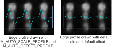
If the drawings made by M_DRAW_..._PROFILE are not at an appropriate scale or location, you can use MmeasSetMarker() with M_DRAW_PROFILE_SCALE_OFFSET to specify a scale and an offset with which to draw. If the M_DRAW_IN_BOX combination constant is applied, you can set the scale and offset to M_AUTO_SCALE_PROFILE and M_AUTO_OFFSET_PROFILE, respectively. In this case, MIL will calculate the greatest scale factor and offset, respectively, that fit the drawing to the area that corresponds to the search region.
Use M_AUTO_SCALE_PROFILE to calculate the maximum scale such that the maximum or minimum of your edgevalues (whichever is larger) touches the ends of the image buffer or the area corresponding to the search region in which the edge profile was established. You can also use an explicit value to specify your own scale. When using M_AUTO_SCALE_PROFILE, the scale is computed after applying the offset. You can specify an explicit offset, or have it calculated automatically using M_AUTO_OFFSET_PROFILE; the latter requires that you also use M_AUTO_SCALE_PROFILE. In this case, the scale and offset are calculated such that both the maximum and the minimum of your edgevalues touch the ends of the destination. When calculating the offset, MIL uses the height of the image buffer or, if the M_DRAW_IN_BOX combination constant is applied, the height of the area that corresponds to the search region. This height is influenced by the orientation of the search region, set using MmeasSetMarker() with M_ORIENTATION.