Search region
- See also

 Availability
 Previous
- Next

-
Box search region (for edge and stripe markers).
-
Ring search region (for circle markers).
-
M_SEARCH_REGION_CLIPPING_MIN_AREA, which allows you to specify a minimum required area for the internally clipped region.
-
M_SEARCH_REGION_CLIPPING_MIN_HEIGHT and M_SEARCH_REGION_CLIPPING_MIN_WIDTH, which allow you to specify a minimum required height and width for the internally clipped region.
-
M_SEARCH_REGION_CLIPPING_PRESERVE_CENTER, which allows you to specify conditions based on the center of the internally clipped region. For example, if you set M_SEARCH_REGION_CLIPPING_PRESERVE_CENTER to M_ALONG_HEIGHT, the internally clipped region will only be valid if the center-position along its height is the same as the center-position along the height of the defined box search region. Similarly, if you set M_ALONG_WIDTH, the internally clipped region can only be valid if the center-position along its width is the same as the center-position along the width of the defined box search region.
-
Ensure that the marker is at its expected (nominal) angle, and that the placement of the box search region is such that MIL finds the marker at an angle that is close to the same as the box's angle.
-
Use MimRotate() to turn the image (which turns the marker) in small increments in the positive direction (for example, +0.5°) and perform an MmeasFindMarker() operation on each rotated image. Ensure that the image's center of rotation is the same as that of the box search region; otherwise, the resulting tolerance will be inaccurate. When rotating the image, always set the angle from the image's original position to avoid interpolating the image more than once.
-
Check the results for the greatest angle with which MIL can find the marker and produce an acceptable score.
-
Repeat steps 2 and 3, rotating the image in the negative direction (for example, -0.5°).
-
Take the minimum of the absolute value of these angles, double it, and set that as the rotation tolerance for the angular search.
Before you can search for a marker, you must define the area in which to perform the search. In general, this area is known as the search region. MIL stores the search region as a characteristic of the marker, which you must set with MmeasSetMarker(). MIL only searches for the marker in the search region.
There are two types of search regions:
If the image you are using has a region of interest (ROI), MIL ignores the position and size of the box or ring search region defined using MmeasSetMarker(), and instead uses the ROI as the search region. To find edge or stripe markers, the ROI must be a rectangular region in vector format (M_VECTOR). To search for circle markers, the ROI must be a ring region in vector format. This does not affect the settings of the box or ring search regions defined using MmeasSetMarker() (these settings can still be recovered using MmeasInquire()), but the results of the find operation will be found based on the position and size of the region of interest (ROI).
To draw the search region defined using MmeasSetMarker(), use MmeasDraw() with M_DRAW_SEARCH_REGION.
Box search region
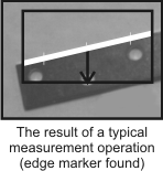
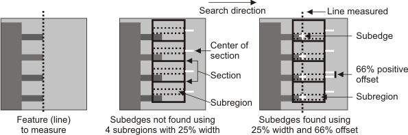
To locate edge and stripe markers, you must use a box (rectangular) search region, defined using MmeasSetMarker() or a rectangular ROI. By default, MIL considers the entire target image as the box search region. The following example shows a target image with a delimited box search region and an edge marker found within it.
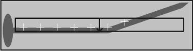
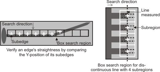
For more advanced applications (such as dealing with crooked edges or edges that are not continuous), you can divide the box search region into sections, and then have MIL process a subregion of each of these sections. In this case, MIL finds and fits a line to points marking the strongest pixel intensity transition for each subregion (rather than for the entire box search region); this can result in better precision. This can be useful to, for example, detect irregularities by comparing the resulting positions of the subedges. In the following example, the Y-position of each subedge is not the same, so it can be deduced that the nail is not straight.
Provided you are using a calibrated image, you can also specify the dimensions of your search region in world units using MmeasSetMarker() with M_MARKER_REFERENCE_INPUT_UNITS (or by using MgraControlList() with M_INPUT_UNITS if the search region was defined using an ROI). By using a calibrated image, you can specify the search region with respect to the relative coordinate system, and then fixture the relative coordinate system to each object. This way, you will only need to place the search region once, and all of the search results will be made from the same reference location.
Setting the size and position of the search region
When defining the box search region using MmeasSetMarker(), set the width and height of the box search region using M_BOX_SIZE. To set the box's position, you must specify the location of either its origin or center, using M_BOX_ORIGIN or M_BOX_CENTER, respectively.
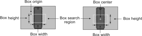
The origin always indicates the top-left corner of the unrotated box search region. When you set the width and height of the box (M_BOX_SIZE), the box expands or shrinks with respect to its origin. When you change M_BOX_SIZE, MIL moves the box's center accordingly (M_BOX_CENTER), while M_BOX_ORIGIN remains fixed.
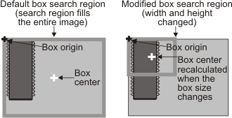
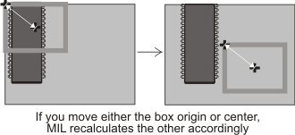
Similarly, if you change M_BOX_ORIGIN, MIL moves M_BOX_CENTER (and vice versa).
When defining the box search region using MmeasSetMarker(), you can use MmeasInquire() to retrieve the box's actual dimensions, as well as the location of its center and origin. To draw the box's center, use MmeasDraw() with M_DRAW_SEARCH_REGION_CENTER.
Regardless of how you are defining the box search region, to help prevent inaccurate results, especially with a detailed or complex target image, you should limit the box search region to as small an area as possible that still contains the marker. To help prevent inaccurate results, especially with a detailed or complex image, the box should fit entirely inside the target image and the edges of the marker should enter and exit on opposite sides of the box search region (although this is not a necessity). If you cannot always adhere to these conditions and are not getting the results you expect, you can try clipping the region or separating it into subregions. For more information, see the Search region clipping subsection of this section and the Subregions of the box search region subsection of this section. In certain cases, MIL requires subregions to perform its calculations and will internally use them even if you did not explicitly specify any, such as when calculating the equation of the line that best follows an edge. For more information, see the Line equation (mean line) subsection of the Search results section later in this chapter.
Using drawings to verify the search region placement
To verify that your search region is in the correct position, you can draw results to get a visual representation of your search region. When using MmeasDraw(), MIL will draw the specified characteristic within the dimensions of the destination image buffer. You can alternatively fit the drawings inside the box search region; to do so, you must add M_DRAW_IN_BOX to the drawing operation (for example, M_DRAW_EDGES_PROFILE + M_DRAW_IN_BOX). When using MmeasDraw(), MIL can shrink or enlarge certain drawings, such as M_DRAW_EDGES_PROFILE, so that they are more readable. For more information on resizing your drawings, see the Retrieving and drawing edge information subsection of the Search algorithm section earlier in this chapter.
Marker orientation and search direction
The marker's orientation specifies the expected direction of the marker's edge transition, relative to that of the box search region. You can set the orientation (M_ORIENTATION) to either vertical (M_VERTICAL) or horizontal (M_HORIZONTAL).
MIL searches for the marker in the direction that is perpendicular to its specified orientation. That is, if you specify that the marker has a vertical orientation, MIL performs the search within the search region from left-to-right; if you specify that the marker has a horizontal orientation, MIL performs the search from top-to-bottom. To draw an arrow indicating the search direction, use MmeasDraw() with M_DRAW_SEARCH_DIRECTION.
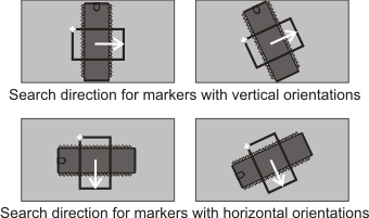
You can also set the orientation to M_ANY; in this case, MIL searches both left-to-right and top-to-bottom.
Search region clipping
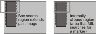
If the search region falls outside the image boundaries, MmeasFindMarker() typically fails. To help manage this, you can set M_SEARCH_REGION_CLIPPING to M_MAXIMIZE_AREA, which allows MIL to try and internally create a clipped version of the search region that it can then search for the marker. MIL creates this region for internal access only; it does not alter the definition of the box search region that you set. This internal (clipped) region represents the maximum area that is both inscribed by the box search region and the image boundaries.
The internally clipped region must always be within the defined (actual) box search region and the image. You can also specify the following M_SEARCH_REGION_CLIPPING_... conditions that must be met by the internally clipped region before MIL considers it a valid area within which it can search for a marker:
If you allow clipping and you reposition the box search region such that it extends past the image boundary, inquiring the size of the box results in the size that you have set, and not the size of the internally clipped region. In the following example, the search region is defined using MmeasSetMarker(). The dimensions of the box search region (M_BOX_SIZE) are set to 180 (width) and 110 (height) pixels, and the box's center is at the center of the image. Repositioning the box's center to (50, 50) causes the box to move and extend past the image boundary.
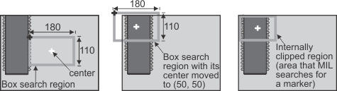
If you inquire the width and height of the box, MIL returns 180 and 110, respectively. If you inquire M_BOX_CENTER, MIL returns (50, 50), while M_BOX_ORIGIN returns the origin position that results from moving the box's center (that is, (-40, -5)).
If you are using subregions and you do not enable clipping, the marker might still be found if the search region is outside the image. For more information on subregions, see the Subregions of the box search region subsection of this section.
Setting the angle of the box search region
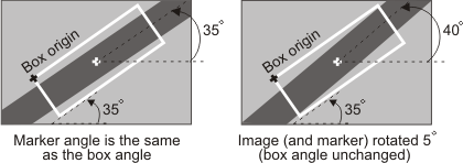
Ideally, the edge or stripe marker should be perpendicular to the search direction of the box search region. The measurement operation can however tolerate a certain amount of rotation. The amount depends on several factors such as the target image, the placement of the box search region, and the marker's characteristic settings. If the rotation is too great, the chance of not finding the marker or miscalculating characteristics, such as edge strength and width, increases. In such cases, you can define the marker's box search region at an angle. The box's angle should be approximately the same angle as its marker. When defining the box search region using MmeasSetMarker(), use M_BOX_ANGLE to specify the angle.
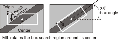
When defining the box search region using MmeasSetMarker(), the angle can be any value from 0 to 360° and should be set counter-clockwise, measured from the positive X-axis. By default, the center of rotation is the center of the box search region. To modify the center of rotation, use MmeasSetMarker() with M_BOX_ANGLE_REFERENCE. You can also have MIL analyze the content of the box search region and automatically determine the best angle for the box, by setting M_BOX_ANGLE to M_ANY (though this technique can increase processing time).
You can use MmeasGetResult() with M_BOX_ANGLE_FOUND to retrieve the angle at which the marker was found.
Multiple-angle search for a marker
If you want to search for a marker within a range of possible angles, you can allow MIL to rotate the box search region by enabling a multiple-angle search, using M_BOX_ANGLE_MODE. In this case, you must set the range of angles to search (M_BOX_ANGLE_DELTA_NEG and M_BOX_ANGLE_DELTA_POS), the degree of rotation tolerance at any given angle (M_BOX_ANGLE_TOLERANCE), the type of interpolation (M_SEARCH_REGION_ANGLE_INTERPOLATION_MODE), and the required degree of accuracy for the resulting marker (M_BOX_ANGLE_ACCURACY).
To perform a multiple-angle search for a marker, MIL first finds its approximate location and angle by searching within the angular range at every n (rotation tolerance) degrees. Once MIL establishes the approximate location of the marker, MIL performs a number of fine-tuned searches, according to the degree of accuracy. To be effective, the degree of accuracy must be less than the rotation tolerance. Note that the rotation tolerance refers to how much MIL can rotate a marker from its box search region and still find it. For more information, see the Determining the rotation tolerance of a marker subsection of this section.
During each step of a multiple-angle search, MIL tries to find the marker with the highest score (M_SCORE_TOTAL); for an edge marker, this is the score of the edge, and for a stripe marker, this is the mean score of both edges. As previously mentioned, you can use MmeasGetResult() with M_BOX_ANGLE_FOUND to retrieve the angle of the box search region at which the marker was found.
If searching within a range of angles causes the box search region to rotate beyond the edges of the target image, you must reposition or resize the box search region unless you are using subregions or allowing for clipping.
Determining the rotation tolerance of a marker
Every marker has its own particular rotation tolerance (the amount by which a marker can be offset from the box search region and still be found). This tolerance is dependent on the marker's individual characteristics and the surrounding image features. When performing a multiple-angle search for a marker, you should specify its rotation tolerance. To determine the tolerance, you can simulate the marker's rotation by turning the target image while maintaining the box search region at a fixed position and angle. That is:
When determining the rotation tolerance of a marker, the box search region must remain at a set position and angle; therefore, you must disable the multiple-angle search (M_BOX_ANGLE_MODE).
Subregions of the box search region
As previously mentioned, you can divide the box search region into sections and have MIL process a subregion of each of these sections. By default, subregions occupy the same area as their section, although you can reduce their size (for example, when the edge is not continuous). Edges within subregions are called subedges.
Subregions typically apply to advanced applications and allow for more precise and complex measurements. For example, you can use the information from subregions to check if an edge is straight, or to find the line equation for a discontinuous edge that is disconnected at regular intervals.
Each subregion acts like an independent box search region (MIL only searches for markers within them). To help prevent inaccurate results, the subedge should be continuous and should enter and exit the entire subregion in the direction that is perpendicular to the search (though this is not a necessity).
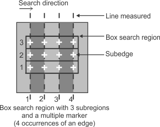
For edge and stripe markers, you can use subregions to find single or multiple-occurrence markers. For example, the following image shows a box search region with three subregions and four occurrences of an edge marker.
To divide the box search region into a certain number of sections, use MmeasSetMarker() with M_SUB_REGIONS_NUMBER. To narrow the subregion in each section, use M_SUB_REGIONS_SIZE, and specify the width of each subregion as a percentage of its section. By default, MIL centers the subregion within its section. To move the subregion, use M_SUB_REGIONS_OFFSET and specify the displacement as a percentage of the maximum possible offset within a section. Depending on the orientation, positive values can shift the subregion right or down, while negative values can shift it left or up. In the following example, the subedges cannot be found within their subregion (in the direction that is perpendicular to the search) until they are offset; only then, can MIL accurately calculate the line.
A minimum of two subregions must be completely inside the target image for the search operation to succeed. This allows for more flexibility in the placement of the box search region when searching through an angular range, because a small part of the box search region is allowed to leave the target image.
In some cases, such as in noisy images, MIL might place subregions at unwanted locations, thereby calculating inaccurate subedges; this can result in, for example, an incorrect line equation. To help solve this problem, you can set a maximum distance between a marker and a subedge (fit point). For more information, see the Maximum association distance of subedges subsection of the Edge markers: advanced characteristics that can be specified section later in this chapter
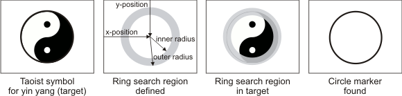
Ring search region
To locate a circle marker, you must use a ring search region, which you can specify with a center point (MmeasSetMarker() with M_RING_CENTER) and an inner and outer radius (M_RING_RADII). When defining the box search region using MmeasSetMarker(), the outer radius must be greater than the inner radius; otherwise, you will receive an error.
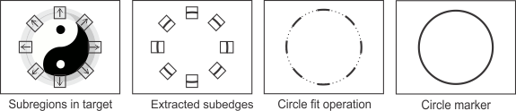
The following animation shows how finding a circle marker in a target image is accomplished:

When defining the box search region using MmeasSetMarker(), MIL considers the center of a ring search region to be its position; to draw it, use MmeasDraw() with M_DRAW_SEARCH_REGION_CENTER.
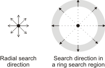
Ring search regions have a radial search direction. That is, MIL searches for a circle marker within a ring search region in an outward direction, around the ring's center point, starting at the ring's inner radius and ending at its outer radius.
Note that, by default, MIL divides the ring search region into eight subregions within which it searches for the circle marker. For more information, see the Subregions of the ring search region subsection of this section. By default, the search uses a nearest neighbor interpolation to locate circle markers. For most applications, this is typically appropriate. However, you can specify a bicubic or bilinear interpolation, using M_SEARCH_REGION_ANGLE_INTERPOLATION_MODE.
Placing the ring search region
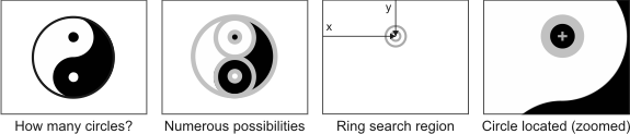
By default, the position of the ring search region is either at the center of the image in the pixel coordinate system, or at the origin of the relative coordinate system, depending on the input coordinate system (set using M_SEARCH_REGION_INPUT_UNITS). Also, by default, the inner radius is 0 and the outer radius is equal to a value that corresponds to the largest possible circle that completely fits within the dimensions of the target image. This results in locating the best circle marker in the entire target image.
Depending on your application, you will likely have to change these defaults; otherwise, incorrect results might occur. Placing the ring search region properly is essential to the success of the measurement operation, and depends on the expected location of the circle.
You should limit the ring search region to as small an area as possible that still contains the circle marker. This increases the chance of success, especially with a detailed or complex target image.
If the ring search region falls outside the image boundaries, the find operation typically fails. As previously discussed with box search regions, you can help manage this using M_SEARCH_REGION_CLIPPING set to M_MAXIMIZE_AREA, which allows MIL to automatically clip the ring search region when it falls outside the image. In this case, MIL internally creates a modified (clipped) version of the search region (it does not alter the actual search region that you set). For more information about how MIL clips the search region, see the Search region clipping subsection of this section. Since the ring search region is split into subregions (discussed later), MIL might still find the circle marker if the ring search region is outside the image and you do not enable clipping.
Subregions of the ring search region
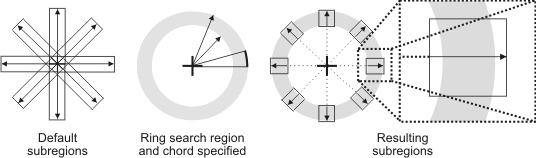
By default, the ring search region internally has eight rectangular subregions that MIL evenly distributes around the center of the ring. Considering the subedges found within the subregions, MIL performs a circle fit operation to locate the circle marker.
Each subregion acts like an independent search region (MIL only searches within them). Ideally, for MIL to find a circle marker, the edge within the subregion (subedge) should be continuous and should enter and exit the entire subregion in the direction that is perpendicular to the search (although this is not a necessity).
Not all subregions must contain a valid edge; MIL requires a minimum of three. Therefore, it is possible to locate a circle even if part of it is missing, or part of it is outside the target image. Though MIL can locate a partial or broken circle, the marker that is found is always a fully closed circle, that is to say that the located subedges will be used to apply a circular fit to the remainder of the circle marker. The edges within the subregions must belong to a single circle; that is, you cannot specify a circle marker as a multiple-occurrence marker.
The distribution of subregions is an internal operation that you cannot modify. However, you can set the number of subregions, using M_SUB_REGIONS_NUMBER. You can specify any value greater than or equal to 8 (default).
The dimension of the subregion, along the side that is parallel to the search direction, is automatically set by the inner and outer radii. However, the dimension of the subregion along the side that is perpendicular to the search direction is set by M_SUB_REGIONS_CHORD_ANGLE. For this setting, you must specify an angle value according to the projected length of the chord (circle segment) that the rectangular subregion must contain. You can specify any angle between 0° and 45°. By default, the angle is 10°.

Note that since a ring search region is circular and its subregions are rectangular, the subregions extend slightly beyond the boundaries of the radii to ensure that they enclose the specified chord.
The default subregions and chord angle that the circle fit operation uses allows for a certain amount of tolerance towards outliers and missing subedges, which is generally sufficient for the majority of applications. However you might need to alter these defaults, particularly if you require greater precision; for example, locating one of two circles that are nearby, or dealing with a particularly noisy or occluded target image.
If altering these defaults, remember to consider the value of both M_SUB_REGIONS_NUMBER and M_SUB_REGIONS_CHORD_ANGLE concurrently, since MIL creates subregions according to both of these settings. Depending on their values, subregions can overlap. In general, more subregions and a smaller chord angle results in a more precise fit of the circle, while too many subregions and too small an angle can result in false positives and longer processing times.
In some cases, such as in noisy images, MIL can place subregions at unwanted locations and perform an incorrect fit of the circle marker. To help solve this problem, you can set a maximum distance between a marker and a subedge (fit point). For more information, see the Maximum association distance of subedges subsection of the Edge markers: advanced characteristics that can be specified section later in this chapter. By default, MIL uses a high level of accuracy to perform the circle's fit operation. However, if you are not dealing with noisy or badly contrasted images, this type of precision might be unnecessary. To lower the accuracy, and possibly the processing time, use with M_CIRCLE_ACCURACY set to M_LOW.
Typically, the fit operation that MIL performs establishes the circle marker within the boundaries of the ring search region's subregions. However, given the circle marker's characteristics and the quality of your image (for example, if there is a lot of noise), MIL can, by default, establish a circle that is outside these boundaries. To specify that MIL must always establish the circle marker within the ring search region (and each of its subregions), set M_CIRCLE_INSIDE_SEARCH_REGION set to M_ENABLE.