MmetSetRegion
| MIL_ID ContextId, | //in |
| MIL_INT FeatureLabelOrIndex, | //in |
| MIL_INT ReferenceFrameLabelOrIndex, | //in |
| MIL_INT64 Geometry, | //in |
| MIL_DOUBLE Param1, | //in |
| MIL_DOUBLE Param2, | //in |
| MIL_DOUBLE Param3, | //in |
| MIL_DOUBLE Param4, | //in |
| MIL_DOUBLE Param5, | //in |
| MIL_DOUBLE Param6 | //in |
This function allows you to set a geometrically-defined ROI, referred to as a metrology region, for a physically measured feature within the template of the metrology context. The metrology region delimits the area in the target image from which to establish the edgels of the feature to validate and measure. When you call this function, you can define the metrology region in one of the following ways.
-
Explicitly specify the shape and size of the region. This is referred to as an explicitly-defined metrology region.
-
Set the region's shape and size using a graphic in a graphics list. This is referred to as a graphics list metrology region.
-
Define the metrology region based on other features by passing a derived metrology region object to this function. This is referred to as a derived metrology region.
When using a graphics list metrology region (M_FROM_GRAPHIC_LIST), the graphics list must contain only one graphic and it must have the same geometric-shape as specified with the Geometry parameter of this function. The advantage of defining a graphics list metrology region is that you can set it with respect to the relative coordinate system as well as set it interactively.
When using a derived metrology region (M_FROM_DERIVED_GEOMETRY_REGION), you must allocate a derived metrology region object using MmetAlloc() with M_DERIVED_GEOMETRY_REGION, and then set it up using MmetControl() with M_REGION_.... Once you specify the geometry of the derived metrology region using the M_REGION_GEOMETRY control type, you can set most of the geometry's attributes either explicitly or derive them based on a feature. Use the corresponding M_REGION_..._TYPE control type to specify which. For example, instead of specifying explicit X- and Y-coordinates to set the position of a rectangular metrology region, you can derive its position according to the position of a point feature.
The metrology region that you choose must be compatible with the type of feature you are adding (MmetAddFeature() with M_MEASURED). For example, when adding a physically measured circle feature, you can use an M_RING metrology.
The metrology region is set according to its feature's reference frame (ReferenceFrameLabelOrIndex). The global frame is the default. If the target image is not calibrated, the global frame's default origin (0,0) is aligned with the center of the top-left corner pixel of the target image. If the target image is calibrated, the global frame's default origin is aligned with the origin of the relative (world) coordinate system. To change the reference frame to a local frame, use MmetControl() with M_REFERENCE_FRAME. Local frames are coordinate systems located anywhere within the metrology template and defined as metrology features.
A valid feature must not only fall within the metrology region, but its edgels' gradient angle must also fall along the region's orientation. Various control types can be used to set a valid relationship between the metrology region's orientation, and the edgels' gradient angle. For more information, see the Gradient angle subsection of the Degrees of freedom section of Chapter 15: Metrology.
Note that you cannot specify a geometrically-defined region for a physically measured feature with a region of interest (ROI) set using MbufSetRegion(); you can only use metrology regions established with this function.
Specifies the identifier of the metrology context containing the template in which to set the metrology region. The metrology context must have been previously allocated on the required system using MmetAlloc().
Specifies the label or index of the measured feature that will be established from the area delimited by the metrology region. Set this parameter to one of the following values.
 For specifying a feature
 |
|||||||||||||||||||||||||||||||||||||||
  Value Value |
Description
|
||||||||||||||||||||||||||||||||||||||
 
|
Specifies the index of an existing individual feature. (more details...) |
||||||||||||||||||||||||||||||||||||||
| Parameters | |||||||||||||||||||||||||||||||||||||||
|
This parameter specifies the index of the measured feature to establish from the metrology region. You can set this parameter to the following: |
|||||||||||||||||||||||||||||||||||||||
|
|||||||||||||||||||||||||||||||||||||||
 
|
Specifies the label value of an existing individual feature. (more details...) |
||||||||||||||||||||||||||||||||||||||
| Parameters | |||||||||||||||||||||||||||||||||||||||
|
This parameter specifies the label of the measured feature to establish from the metrology region. You can set this parameter to the following: |
|||||||||||||||||||||||||||||||||||||||
|
|||||||||||||||||||||||||||||||||||||||
Specifies the label or index of the reference frame feature of the physically measured feature for which you are specifying a metrology region. To change the reference frame, use MmetControl() with M_REFERENCE_FRAME.
 For specifying the reference
frame
 |
|||||||||||||||||||||||||||||||||||||||
  Value Value |
Description
|
||||||||||||||||||||||||||||||||||||||
  M_DEFAULT
 |
Same as M_GLOBAL_FRAME. |
||||||||||||||||||||||||||||||||||||||
 
|
Specifies the index value of an existing reference frame feature. (more details...) |
||||||||||||||||||||||||||||||||||||||
| Parameters | |||||||||||||||||||||||||||||||||||||||
|
This parameter specifies the index of the reference frame feature. You can set this parameter to the following: |
|||||||||||||||||||||||||||||||||||||||
|
|||||||||||||||||||||||||||||||||||||||
 
|
Specifies the label value of an existing reference frame feature. (more details...) |
||||||||||||||||||||||||||||||||||||||
| Parameters | |||||||||||||||||||||||||||||||||||||||
|
This parameter specifies the label of the reference frame feature. You can set this parameter to the following: |
|||||||||||||||||||||||||||||||||||||||
|
|||||||||||||||||||||||||||||||||||||||
  M_GLOBAL_FRAME M_GLOBAL_FRAME |
Specifies the global frame as the reference frame. |
||||||||||||||||||||||||||||||||||||||
Specifies the geometric shape of the metrology region.
See the Parameter associations section for possible values that can be specified.
Specifies an attribute of the metrology region to set. Its definition is dependent on the geometry chosen.
See the Parameter associations section for possible values that can be specified.
Specifies an attribute of the metrology region to set. Its definition is dependent on the geometry chosen.
Set this parameter to M_NULL if not used.
See the Parameter associations section for possible values that can be specified.
Specifies an attribute of the metrology region to set. Its definition is dependent on the geometry chosen.
Set this parameter to M_NULL if not used.
See the Parameter associations section for possible values that can be specified.
Specifies an attribute of the metrology region to set. Its definition is dependent on the geometry chosen.
Set this parameter to M_NULL if not used.
See the Parameter associations section for possible values that can be specified.
Specifies an attribute of the metrology region to set. Its definition is dependent on the geometry chosen.
Set this parameter to M_NULL if not used.
See the Parameter associations section for possible values that can be specified.
Specifies an attribute of the metrology region to set. Its definition is dependent on the geometry chosen.
Set this parameter to M_NULL if not used.
See the Parameter associations section for possible values that can be specified.
The tables below list possible values for the Geometry, Param1, Param2, Param3, Param4, Param5, and Param6 parameters.
The following can be specified for setting an explicitly-defined metrology region. To specify a graphics list metrology region, you must add M_FROM_GRAPHIC_LIST to the supported geometry (M_ARC, M_RECTANGLE, and M_SEGMENT).
Unused parameters should be set to M_NULL.
 For setting an explicitly-defined or
graphics list metrology region
 |
|||||||||||||||||||||||||||||||||||||||
  Geometry Geometry |
Description
|
||||||||||||||||||||||||||||||||||||||
| Param1 | |||||||||||||||||||||||||||||||||||||||
| Param2 | |||||||||||||||||||||||||||||||||||||||
| Param3 | |||||||||||||||||||||||||||||||||||||||
| Param4 | |||||||||||||||||||||||||||||||||||||||
| Param5 | |||||||||||||||||||||||||||||||||||||||
| Param6 | |||||||||||||||||||||||||||||||||||||||
  M_DEFAULT
 |
Same as M_INFINITE. (more details...) |
||||||||||||||||||||||||||||||||||||||
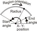
  M_ARC +
 |
Specifies that the feature will be established from an arc metrology region. (more details...) |
||||||||||||||||||||||||||||||||||||||
  Param1 Param1 |
Sets the X-coordinate of the origin of the arc metrology region, relative to the reference frame. INQ (more details...) |
||||||||||||||||||||||||||||||||||||||
  M_DEFAULT M_DEFAULT |
Specifies the default value; the default value is 0.0. |
||||||||||||||||||||||||||||||||||||||
  Value
Value |
Specifies the origin's X-coordinate, in pixel or world units. |
||||||||||||||||||||||||||||||||||||||
  Param2 Param2 |
Sets the Y-coordinate of the origin of the arc metrology region, relative to the reference frame. INQ (more details...) |
||||||||||||||||||||||||||||||||||||||
  M_DEFAULT M_DEFAULT |
Specifies the default value; the default value is 0.0. |
||||||||||||||||||||||||||||||||||||||
  Value
Value |
Specifies the origin's Y-coordinate, in pixel or world units. |
||||||||||||||||||||||||||||||||||||||
  Param3 Param3 |
Sets the radius of the arc metrology region. INQ (more details...) |
||||||||||||||||||||||||||||||||||||||
  M_DEFAULT M_DEFAULT |
Specifies the default value; the default value is 0.0 pixels. |
||||||||||||||||||||||||||||||||||||||
  Value
Value |
Specifies the radius, in pixel or world units. |
||||||||||||||||||||||||||||||||||||||
  Param4 Param4 |
Sets the start angle of the arc metrology region, relative to the reference frame. INQ (more details...) |
||||||||||||||||||||||||||||||||||||||
  M_DEFAULT M_DEFAULT |
Specifies the default value; the default value is 0.0°. |
||||||||||||||||||||||||||||||||||||||
  0.0 <= Value <= 360.0
 |
Specifies the angle, in degrees. |
||||||||||||||||||||||||||||||||||||||
  Param5 Param5 |
Sets the end angle of the arc metrology region, relative to the reference frame. INQ (more details...) |
||||||||||||||||||||||||||||||||||||||
  M_DEFAULT M_DEFAULT |
Specifies the default value; the default value is 360.0°. |
||||||||||||||||||||||||||||||||||||||
  0.0 <= Value <= 360.0
 |
Specifies the angle, in degrees. |
||||||||||||||||||||||||||||||||||||||
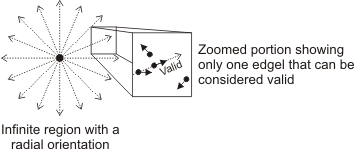
  M_INFINITE
 |
Specifies that the feature will be established from an infinite metrology region. (more details...) |
||||||||||||||||||||||||||||||||||||||
  Param1 Param1 |
Sets the X-coordinate of the origin of the infinite metrology region, relative to the reference frame. INQ (more details...) |
||||||||||||||||||||||||||||||||||||||
  M_DEFAULT M_DEFAULT |
Specifies the default value; the default value is 0.0. |
||||||||||||||||||||||||||||||||||||||
  Value Value |
Specifies the origin's X-coordinate, in pixel or world units. |
||||||||||||||||||||||||||||||||||||||
  Param2 Param2 |
Sets the Y-coordinate of the origin of the infinite metrology region, relative to the reference frame. INQ (more details...) |
||||||||||||||||||||||||||||||||||||||
  M_DEFAULT M_DEFAULT |
Specifies the default value; the default value is 0.0. |
||||||||||||||||||||||||||||||||||||||
  Value Value |
Specifies the origin's Y-coordinate, in pixel or world units. |
||||||||||||||||||||||||||||||||||||||
  Param3 Param3 |
Sets the angle (orientation) of the infinite metrology region, relative to the reference frame. INQ (more details...) |
||||||||||||||||||||||||||||||||||||||
  M_DEFAULT M_DEFAULT |
Specifies the default value; the default value is 0.0°. (more details...) |
||||||||||||||||||||||||||||||||||||||
  M_RADIAL M_RADIAL |
Specifies that the infinite metrology region has a radial orientation, from 0.0° to 360.0°, based on the specified origin. (more details...) |
||||||||||||||||||||||||||||||||||||||
  0.0 <= Value <=
360.0
 |
Specifies the angle, in degrees, relative to the reference frame. (more details...) |
||||||||||||||||||||||||||||||||||||||
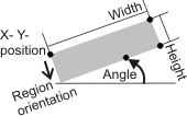
  M_RECTANGLE + M_RECTANGLE + |
Specifies that the feature will be established from a rectangular metrology region. (more details...) |
||||||||||||||||||||||||||||||||||||||
  Param1 Param1 |
Sets the X-coordinate of the origin of the rectangular metrology region, relative to the reference frame. INQ (more details...) |
||||||||||||||||||||||||||||||||||||||
  M_DEFAULT M_DEFAULT |
Specifies the default value; the default value is 0.0. |
||||||||||||||||||||||||||||||||||||||
  Value Value |
Specifies the origin's X-coordinate, in pixel or world units. |
||||||||||||||||||||||||||||||||||||||
  Param2 Param2 |
Sets the Y-coordinate of the origin of the rectangular metrology region, relative to the reference frame. INQ (more details...) |
||||||||||||||||||||||||||||||||||||||
  M_DEFAULT M_DEFAULT |
Specifies the default value; the default value is 0.0. |
||||||||||||||||||||||||||||||||||||||
  Value Value |
Specifies the origin's Y-coordinate, in pixel or world units. |
||||||||||||||||||||||||||||||||||||||
  Param3 Param3 |
Sets the width of the rectangle. INQ (more details...) |
||||||||||||||||||||||||||||||||||||||
  M_DEFAULT M_DEFAULT |
Specifies the default value; the default value is 0.0 pixels. |
||||||||||||||||||||||||||||||||||||||
  Value Value |
Specifies the rectangle's width, in pixel or world units. |
||||||||||||||||||||||||||||||||||||||
  Param4 Param4 |
Sets the height of the rectangle. INQ (more details...) |
||||||||||||||||||||||||||||||||||||||
  M_DEFAULT M_DEFAULT |
Specifies the default value; the default value is 0.0 pixels. |
||||||||||||||||||||||||||||||||||||||
  Value Value |
Specifies the rectangle's height, in pixel or world units. |
||||||||||||||||||||||||||||||||||||||
  Param5 Param5 |
Sets the angle (orientation) of the rectangular metrology region, relative to the reference frame. INQ (more details...) |
||||||||||||||||||||||||||||||||||||||
  M_DEFAULT M_DEFAULT |
Specifies the default value; the default value is 0.0°. |
||||||||||||||||||||||||||||||||||||||
  0.0 <= Value <=
360.0
 |
Specifies the angle, in degrees. |
||||||||||||||||||||||||||||||||||||||
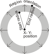
  M_RING
 |
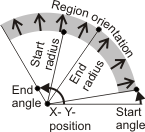
Specifies that the feature will be established from a ring-shaped metrology region. (more details...) |
||||||||||||||||||||||||||||||||||||||
  Param1 Param1 |
Sets the X-coordinate of the center of the ring-shaped metrology region, relative to the reference frame. INQ (more details...) |
||||||||||||||||||||||||||||||||||||||
  M_DEFAULT M_DEFAULT |
Specifies the default value; the default value is 0.0. |
||||||||||||||||||||||||||||||||||||||
  Value Value |
Specifies the origin's X-coordinate, in pixel or world units. |
||||||||||||||||||||||||||||||||||||||
  Param2 Param2 |
Sets the Y-coordinate of the center of the ring-shaped metrology region, relative to the reference frame. INQ (more details...) |
||||||||||||||||||||||||||||||||||||||
  M_DEFAULT M_DEFAULT |
Specifies the default value; the default value is 0.0. |
||||||||||||||||||||||||||||||||||||||
  Value Value |
Specifies the origin's Y-coordinate, in pixel or world units. |
||||||||||||||||||||||||||||||||||||||
  Param3 Param3 |
Sets the start radius of the ring-shaped metrology region. INQ (more details...) |
||||||||||||||||||||||||||||||||||||||
  M_DEFAULT M_DEFAULT |
Specifies the default value; the default value is 0.0 pixels. |
||||||||||||||||||||||||||||||||||||||
  Value Value |
Specifies the start radius, in pixel or world units. |
||||||||||||||||||||||||||||||||||||||
  Param4 Param4 |
Sets the end radius of the ring-shaped metrology region. INQ (more details...) |
||||||||||||||||||||||||||||||||||||||
  M_DEFAULT M_DEFAULT |
Specifies the default value; the default value is 0.0 pixels. |
||||||||||||||||||||||||||||||||||||||
  Value Value |
Specifies the end radius, in pixel or world units. |
||||||||||||||||||||||||||||||||||||||
  M_RING_SECTOR M_RING_SECTOR |
Specifies that the feature will be established from a ring-sector metrology region. (more details...) |
||||||||||||||||||||||||||||||||||||||
  Param1 Param1 |
Sets the X-coordinate of the origin of the ring-sector metrology region, relative to the reference frame. INQ (more details...) |
||||||||||||||||||||||||||||||||||||||
  M_DEFAULT M_DEFAULT |
Specifies the default value; the default value is 0.0. |
||||||||||||||||||||||||||||||||||||||
  Value Value |
Specifies the origin's X-coordinate, in pixel or world units. |
||||||||||||||||||||||||||||||||||||||
  Param2 Param2 |
Sets the Y-coordinate of the origin of the ring-sector metrology region, relative to the reference frame. INQ (more details...) |
||||||||||||||||||||||||||||||||||||||
  M_DEFAULT M_DEFAULT |
Specifies the default value; the default value is 0.0. |
||||||||||||||||||||||||||||||||||||||
  Value Value |
Specifies the origin's Y-coordinate, in pixel or world units. |
||||||||||||||||||||||||||||||||||||||
  Param3 Param3 |
Sets the start radius of the ring-sector metrology region, relative to the reference frame. INQ (more details...) |
||||||||||||||||||||||||||||||||||||||
  M_DEFAULT M_DEFAULT |
Specifies the default value; the default value is 0.0 pixels. |
||||||||||||||||||||||||||||||||||||||
  Value Value |
Specifies the start radius, in pixel or world units. |
||||||||||||||||||||||||||||||||||||||
  Param4 Param4 |
Sets the end radius of the ring-sector metrology region, relative to the reference frame. INQ (more details...) |
||||||||||||||||||||||||||||||||||||||
  M_DEFAULT M_DEFAULT |
Specifies the default value; the default value is 0.0 pixels. |
||||||||||||||||||||||||||||||||||||||
  Value Value |
Specifies the end radius, in pixel or world units. |
||||||||||||||||||||||||||||||||||||||
  Param5 Param5 |
Sets the start angle of the ring-sector metrology region, relative to the reference frame. INQ (more details...) |
||||||||||||||||||||||||||||||||||||||
  M_DEFAULT M_DEFAULT |
Specifies the default value; the default value is 0.0°. |
||||||||||||||||||||||||||||||||||||||
  0.0 <= Value <=
360.0
 |
Specifies the angle, in degrees. |
||||||||||||||||||||||||||||||||||||||
  Param6 Param6 |
Sets the end angle of the ring-sector metrology region, relative to the reference frame. INQ (more details...) |
||||||||||||||||||||||||||||||||||||||
  M_DEFAULT M_DEFAULT |
Specifies the default value; the default value is 360.0°. |
||||||||||||||||||||||||||||||||||||||
  0.0 <= Value <=
360.0
 |
Specifies the angle, in degrees. |
||||||||||||||||||||||||||||||||||||||
  M_SEGMENT +
 |
Specifies that the feature will be established from a linear segment metrology region. (more details...) |
||||||||||||||||||||||||||||||||||||||
  Param1 Param1 |
Sets the X-coordinate of the start point of the segment metrology region, relative to the reference frame. INQ (more details...) |
||||||||||||||||||||||||||||||||||||||
  M_DEFAULT M_DEFAULT |
Specifies the default value; the default value is 0.0. |
||||||||||||||||||||||||||||||||||||||
  Value Value |
Specifies the start point's X-coordinate, in pixel or world units. |
||||||||||||||||||||||||||||||||||||||
  Param2 Param2 |
Sets the Y-coordinate of the start point of the segment metrology region, relative to the reference frame. INQ (more details...) |
||||||||||||||||||||||||||||||||||||||
  M_DEFAULT M_DEFAULT |
Specifies the default value; the default value is 0.0. |
||||||||||||||||||||||||||||||||||||||
  Value Value |
Specifies the start point's Y-coordinate, in pixel or world units. |
||||||||||||||||||||||||||||||||||||||
  Param3 Param3 |
Sets the X-coordinate of the end point of the segment metrology region, relative to the reference frame. INQ (more details...) |
||||||||||||||||||||||||||||||||||||||
  M_DEFAULT M_DEFAULT |
Specifies the default value; the default value is 0.0. |
||||||||||||||||||||||||||||||||||||||
  Value Value |
Specifies the end point's X-coordinate, in pixel or world units. |
||||||||||||||||||||||||||||||||||||||
  Param4 Param4 |
Sets the Y-coordinate of the end point of the segment metrology region, relative to the reference frame. INQ (more details...) |
||||||||||||||||||||||||||||||||||||||
  M_DEFAULT M_DEFAULT |
Specifies the default value; the default value is 0.0. |
||||||||||||||||||||||||||||||||||||||
  Value Value |
Specifies the end point's Y-coordinate, in pixel or world units. |
||||||||||||||||||||||||||||||||||||||
You can add the following value to the above-mentioned values to set a graphics list metrology region.
Unused parameters should be set to M_NULL.
 For setting a graphics list metrology
region
 |
|||||||||||||||||||||||||||||||||||||||
  Geometry Geometry |
Description
|
||||||||||||||||||||||||||||||||||||||
| Param1 | |||||||||||||||||||||||||||||||||||||||
| Param2 | |||||||||||||||||||||||||||||||||||||||
| Param3 | |||||||||||||||||||||||||||||||||||||||
| Param4 | |||||||||||||||||||||||||||||||||||||||
| Param5 | |||||||||||||||||||||||||||||||||||||||
| Param6 | |||||||||||||||||||||||||||||||||||||||
  M_FROM_GRAPHIC_LIST M_FROM_GRAPHIC_LIST |
Specifies a graphics list metrology region. (more details...) |
||||||||||||||||||||||||||||||||||||||
  Param1 Param1 |
Sets the identifier of the graphics list with which to delimit the metrology region. (more details...) |
||||||||||||||||||||||||||||||||||||||
The following can be specified for setting a derived metrology region.
Unused parameters should be set to M_NULL.
 For setting a derived metrology
region
 |
|||||||||||||||||||||||||||||||||||||||
  Geometry Geometry |
Description
|
||||||||||||||||||||||||||||||||||||||
| Param1 | |||||||||||||||||||||||||||||||||||||||
| Param2 | |||||||||||||||||||||||||||||||||||||||
| Param3 | |||||||||||||||||||||||||||||||||||||||
| Param4 | |||||||||||||||||||||||||||||||||||||||
| Param5 | |||||||||||||||||||||||||||||||||||||||
| Param6 | |||||||||||||||||||||||||||||||||||||||
  M_FROM_DERIVED_GEOMETRY_REGION M_FROM_DERIVED_GEOMETRY_REGION |
Specifies a derived metrology region. (more details...) |
||||||||||||||||||||||||||||||||||||||
  Param1 Param1 |
Sets the identifier of the derived metrology region object. (more details...) |
||||||||||||||||||||||||||||||||||||||
|
void MmetSetRegionInt64
(MIL_ID ContextId,
MIL_INT FeatureLabelOrIndex,
MIL_INT
ReferenceFrameLabelOrIndex, MIL_INT64 Geometry,
MIL_INT64 Param1,
MIL_DOUBLE Param2,
MIL_DOUBLE Param3,
MIL_DOUBLE Param4,
MIL_DOUBLE Param5,
MIL_DOUBLE Param6)
Parameters
ContextId See ContextId of the main function for a description. FeatureLabelOrIndex See FeatureLabelOrIndex of the main function for a description. ReferenceFrameLabelOrIndex See ReferenceFrameLabelOrIndex of the main function for a description. Geometry See Geometry of the main function for a description. Param1 See Param1 of the main function for a description. Param2 See Param2 of the main function for a description. Param3 See Param3 of the main function for a description. Param4 See Param4 of the main function for a description. Param5 See Param5 of the main function for a description. Param6 See Param6 of the main function for a description. |
| Header | Include mil.h. |
| Library | Use mil.lib; milmetrol.lib. |
| DLL | Requires mil.dll; milmetrol.dll. |
