
Filters
Filter values by
- General bead settings
- Bead template settings
- Training related settings
- Extraction related settings
- Verification settings
 Availability
 Function map
 | MIL_ID ContextBeadId, | //in |
| MIL_INT LabelOrIndex, | //in |
| MIL_INT64 ControlType, | //in |
| MIL_DOUBLE ControlValue | //in |
This function allows you to control the specified setting for a bead context, or for the templates contained within the context. You can use these settings to manage the training (MbeadTrain()) and verification phases (MbeadVerify()). You can inquire most of these settings using MbeadInquire().
Settings for the training phase have an indirect affect on the verification phase, since it uses trained templates. Therefore if you modify a training phase setting, or a setting that applies to both the training and verification phases, you must re-call MbeadTrain() before the next call to MbeadVerify(). Settings that are exclusively for the verification phase are not used by, and have no effect on, the training phase; if you modify such settings, you need not re-call MbeadTrain().
This function's settings affect either the template's training status (established after calling MbeadTrain()) or verification status (established after calling MbeadVerify()). Depending on the status, you might have to adjust the related settings. To retrieve information about the training status, use MbeadInquire() with M_STATUS; to retrieve information about the verification status, use MbeadGetResult() with M_STATUS.
You can also use this function to control operations with MbeadGetNeighbors().
If you are specifying pixel units, make sure the pixel sizes are consistent across all camera calibrations (for example, pixel sizes should be the same in the training and verification images). When using different camera calibration contexts, it is recommended that you use world units.
Specifies the identifier of the bead context to control. The bead context must have been previously allocated on the required system using MbeadAlloc().
Specifies the bead template (one or all) to control, or specifies that you are controlling a global setting of the bead context. This parameter should be set to one of the following values:
|
For specifying what to control |
|||||||||||||||||||||||||||||||||||||||
| Description | |||||||||||||||||||||||||||||||||||||||
|
Same as M_CONTEXT. |
|||||||||||||||||||||||||||||||||||||||
|
Specifies the index of an existing template to control. (summarize)Specifies the index of an existing template to control. (more details...) |
|||||||||||||||||||||||||||||||||||||||
| Parameters | |||||||||||||||||||||||||||||||||||||||
|
Specifies the index. The index must be greater than or equal to 0. |
|||||||||||||||||||||||||||||||||||||||
|
Specifies the label of an existing template to control. (summarize)Specifies the label of an existing template to control. (more details...) |
|||||||||||||||||||||||||||||||||||||||
| Parameters | |||||||||||||||||||||||||||||||||||||||
|
Specifies the label. The label must be greater than 0. |
|||||||||||||||||||||||||||||||||||||||
|
Applies the specified control setting to all the templates contained within the bead context. In this case, the control type setting must be supported by all the templates. (summarize)Applies the specified control setting to all the templates contained within the bead context. (more details...) |
|||||||||||||||||||||||||||||||||||||||
|
Controls a global setting of a bead context. |
|||||||||||||||||||||||||||||||||||||||
Specifies the type of control to set.
See the Parameter associations section for possible values that can be specified.
Specifies the required value for the control.
See the Parameter associations section for possible values that can be specified.
The tables below list possible values for the ControlType and ControlValue parameters.
The following ControlType and corresponding ControlValue parameter settings are used to control templates (one or all) in a bead context for the training phase (MbeadTrain()). In this case, you must set the LabelOrIndex parameter to a specific template (M_TEMPLATE_INDEX() or M_TEMPLATE_LABEL()) or to all templates (M_ALL).
|
To control bead templates for the training
phase
|
|||||||||||||||||||||||||||||||||||||||
|
|
Description | ||||||||||||||||||||||||||||||||||||||
| ControlValue | |||||||||||||||||||||||||||||||||||||||
|
Sets how MIL establishes the nominal pixel intensity of the template. You can use the pixel intensity of the template when verifying beads. That is, MIL can validate the brightness of each measured point according to the brightness of its associated trained point. MIL calculates the intensity for each point at the center of its corresponding bead width. You can only use this value with stripe-beads. INQ (summarize)Sets how MIL establishes the nominal pixel intensity of the template. INQ (more details...) |
|||||||||||||||||||||||||||||||||||||||
|
Same as M_DISABLE. |
|||||||||||||||||||||||||||||||||||||||
|
Specifies to establish the nominal pixel intensity from the training image. |
|||||||||||||||||||||||||||||||||||||||
|
Specifies that M_INTENSITY_NOMINAL_MODE has no effect. |
|||||||||||||||||||||||||||||||||||||||
|
Specifies that you will explicitly set the pixel intensity, using M_INTENSITY_NOMINAL. |
|||||||||||||||||||||||||||||||||||||||
|
Sets the X-coordinate of the center of a template whose path follows a circle. This value only applies if M_TRAINING_PATH is set to M_CIRCLE. INQ (summarize)Sets the X-coordinate of the center of a template whose path follows a circle. INQ (more details...) |
|||||||||||||||||||||||||||||||||||||||
|
Specifies the default value; the default value is 0.0. |
|||||||||||||||||||||||||||||||||||||||
|
Specifies the center's X-coordinate, relative to the input coordinate system specified using M_TEMPLATE_INPUT_UNITS. |
|||||||||||||||||||||||||||||||||||||||
|
Sets the Y-coordinate of the center of a template whose path follows a circle. This value only applies if M_TRAINING_PATH is set to M_CIRCLE. INQ (summarize)Sets the Y-coordinate of the center of a template whose path follows a circle. INQ (more details...) |
|||||||||||||||||||||||||||||||||||||||
|
Specifies the default value; the default value is 0.0. |
|||||||||||||||||||||||||||||||||||||||
|
Specifies the center's Y-coordinate, relative to the input coordinate system specified using M_TEMPLATE_INPUT_UNITS. |
|||||||||||||||||||||||||||||||||||||||
|
Sets the radius of a template whose path follows a circle. This value only applies if M_TRAINING_PATH is set to M_CIRCLE. INQ (summarize)Sets the radius of a template whose path follows a circle. INQ (more details...) |
|||||||||||||||||||||||||||||||||||||||
|
Specifies the default value; the default value is 0.0. |
|||||||||||||||||||||||||||||||||||||||
|
Specifies the radius, relative to the input coordinate system specified using M_TEMPLATE_INPUT_UNITS. |
|||||||||||||||||||||||||||||||||||||||
|
Sets the units with which to interpret the M_CLOSEST_POINT_MAX_DISTANCE, M_FAIL_WARNING_OFFSET, M_GAP_MAX_LENGTH, M_OFFSET_MAX, M_TEMPLATE_CIRCLE_CENTER_X, M_TEMPLATE_CIRCLE_CENTER_Y, M_TEMPLATE_CIRCLE_RADIUS, M_TEMPLATE_SEGMENT_END_X, M_TEMPLATE_SEGMENT_END_Y, M_TEMPLATE_SEGMENT_START_X, M_TEMPLATE_SEGMENT_START_Y, M_WIDTH_DELTA_NEG, M_WIDTH_DELTA_POS, and M_WIDTH_NOMINAL control types, as well as the units with which to interpret the template's position and dimension values specified using MbeadTemplate(). This essentially sets the input coordinate system to use. INQ (summarize)Sets the units with which to interpret the M_CLOSEST_POINT_MAX_DISTANCE, M_FAIL_WARNING_OFFSET, M_GAP_MAX_LENGTH, M_OFFSET_MAX, M_TEMPLATE_CIRCLE_CENTER_X, M_TEMPLATE_CIRCLE_CENTER_Y, M_TEMPLATE_CIRCLE_RADIUS, M_TEMPLATE_SEGMENT_END_X, M_TEMPLATE_SEGMENT_END_Y, M_TEMPLATE_SEGMENT_START_X, M_TEMPLATE_SEGMENT_START_Y, M_WIDTH_DELTA_NEG, M_WIDTH_DELTA_POS, and M_WIDTH_NOMINAL control types, as well as the units with which to interpret the template's position and dimension values specified using MbeadTemplate(). INQ (more details...) |
|||||||||||||||||||||||||||||||||||||||
|
Same as M_PIXEL. |
|||||||||||||||||||||||||||||||||||||||
|
Specifies to interpret the values in pixel units, with respect to the pixel coordinate system. |
|||||||||||||||||||||||||||||||||||||||
|
Specifies to interpret the values in world units, with respect to the relative coordinate system. If world units are specified, calling MbeadDraw() to draw features of the template, or calling MbeadTrain() or MbeadVerify() generates an error if the operation is not performed on a calibrated image. (summarize)Specifies to interpret the values in world units, with respect to the relative coordinate system. (more details...) |
|||||||||||||||||||||||||||||||||||||||
|
Sets the X-coordinate of the end of a template whose path follows a segment. This value only applies if M_TRAINING_PATH is set to M_SEGMENT. INQ (summarize)Sets the X-coordinate of the end of a template whose path follows a segment. INQ (more details...) |
|||||||||||||||||||||||||||||||||||||||
|
Specifies the default value; the default value is 0.0. |
|||||||||||||||||||||||||||||||||||||||
|
Specifies the X-coordinate of the end of the segment, relative to the input coordinate system specified using M_TEMPLATE_INPUT_UNITS. |
|||||||||||||||||||||||||||||||||||||||
|
Sets the Y-coordinate of the end of a template whose path follows a segment. This value only applies if M_TRAINING_PATH is set to M_SEGMENT. INQ (summarize)Sets the Y-coordinate of the end of a template whose path follows a segment. INQ (more details...) |
|||||||||||||||||||||||||||||||||||||||
|
Specifies the default value; the default value is 0.0. |
|||||||||||||||||||||||||||||||||||||||
|
Specifies the Y-coordinate of the end of the segment, relative to the input coordinate system specified using M_TEMPLATE_INPUT_UNITS. |
|||||||||||||||||||||||||||||||||||||||
|
Sets the X-coordinate of the start of a template whose path follows a segment. This value only applies if M_TRAINING_PATH is set to M_SEGMENT. INQ (summarize)Sets the X-coordinate of the start of a template whose path follows a segment. INQ (more details...) |
|||||||||||||||||||||||||||||||||||||||
|
Specifies the default value; the default value is 0.0. |
|||||||||||||||||||||||||||||||||||||||
|
Specifies the X-coordinate of the start of the segment, relative to the input coordinate system specified using M_TEMPLATE_INPUT_UNITS. |
|||||||||||||||||||||||||||||||||||||||
|
Sets the Y-coordinate of the start of a template whose path follows a segment. This value only applies if M_TRAINING_PATH is set to M_SEGMENT. INQ (summarize)Sets the Y-coordinate of the start of a template whose path follows a segment. INQ (more details...) |
|||||||||||||||||||||||||||||||||||||||
|
Specifies the default value; the default value is 0.0. |
|||||||||||||||||||||||||||||||||||||||
|
Specifies the Y-coordinate of the start of the segment, relative to the input coordinate system specified using M_TEMPLATE_INPUT_UNITS. |
|||||||||||||||||||||||||||||||||||||||
|
Sets the height of the training box in which to establish the trained points. 
When you call MbeadTrain(), MIL uses the specified height of the training box to achieve the best height value based on all your settings (for example, if you use a training image). To inquire the actual height MIL establishes (the trained height), use MbeadInquire() with M_TRAINED_BOX_HEIGHT. INQ (summarize)Sets the height of the training box in which to establish the trained points. INQ (more details...) |
|||||||||||||||||||||||||||||||||||||||
|
Specifies the default value; the default value is 10.0. |
|||||||||||||||||||||||||||||||||||||||
|
Specifies the height, relative to the input coordinate system specified using M_TRAINING_BOX_INPUT_UNITS. |
|||||||||||||||||||||||||||||||||||||||
|
Sets the units with which to interpret the M_TRAINING_BOX_HEIGHT, M_TRAINING_BOX_WIDTH, M_TRAINING_BOX_SPACING, and M_TRAINING_WIDTH_NOMINAL control types. This essentially sets the input coordinate system to use. INQ (summarize)Sets the units with which to interpret the M_TRAINING_BOX_HEIGHT, M_TRAINING_BOX_WIDTH, M_TRAINING_BOX_SPACING, and M_TRAINING_WIDTH_NOMINAL control types. INQ (more details...) |
|||||||||||||||||||||||||||||||||||||||
|
Same as M_PIXEL. |
|||||||||||||||||||||||||||||||||||||||
|
Specifies to interpret the values in pixel units, with respect to the pixel coordinate system. |
|||||||||||||||||||||||||||||||||||||||
|
Specifies to interpret the values in world units, with respect to the relative coordinate system. If world units are specified, calling MbeadDraw() to draw features of the template, or calling MbeadTrain() or MbeadVerify(), generates an error if the operation is not performed on a calibrated image. (summarize)Specifies to interpret the values in world units, with respect to the relative coordinate system. (more details...) |
|||||||||||||||||||||||||||||||||||||||
|
Sets the distance between the center of the training boxes in which to establish the trained points. Since MIL establishes trained points at regular intervals along the template's path, the specified spacing is adjusted accordingly. To inquire the actual spacing MIL uses, call MbeadInquire() with M_TRAINED_BOX_SPACING. INQ (summarize)Sets the distance between the center of the training boxes in which to establish the trained points. INQ (more details...) |
|||||||||||||||||||||||||||||||||||||||
|
Specifies the default value; the default value is 10.0. |
|||||||||||||||||||||||||||||||||||||||
|
Specifies that M_TRAINING_BOX_SPACING has no effect. If a template's path follows a fixed circle or a segment (M_TRAINING_PATH set to M_CIRCLE or M_SEGMENT) and you disable spacing, MIL internally creates the minimum number of critical points required to geometrically establish the path. If a template's path follows a fixed polyline (M_POLYLINE) and you disable spacing, the trained points will be the same as the vertices specified when adding or modifying the template (MbeadTemplate()). Such vertices can, for example, come from a CAD file, where the exact path of the polyline is known (but not necessarily the width). If a template's path follows a polyline that is refined by a training image (M_POLYLINE_SEED) and you disable spacing, the number of trained points will be the same as the number of vertices specified when adding or modifying the template (MbeadTemplate()), however MIL will reposition them accordingly (with respect to the training image). (summarize)Specifies that M_TRAINING_BOX_SPACING has no effect. (more details...) |
|||||||||||||||||||||||||||||||||||||||
|
Specifies the spacing, relative to the input coordinate system specified using M_TRAINING_BOX_INPUT_UNITS. |
|||||||||||||||||||||||||||||||||||||||
|
Sets the width of the training box in which to establish the trained points. 
When you call MbeadTrain(), MIL uses the specified width of the training box to achieve the best width value based on all your settings (for example, if you use a training image). To inquire the actual width MIL establishes (the trained width), use MbeadInquire() with M_TRAINED_BOX_WIDTH. Note that MIL does not typically alter the specified training box width. INQ (summarize)Sets the width of the training box in which to establish the trained points. INQ (more details...) |
|||||||||||||||||||||||||||||||||||||||
|
Specifies the default value; the default value is 200.0. |
|||||||||||||||||||||||||||||||||||||||
|
Specifies the width, relative to the input coordinate system specified using M_TRAINING_BOX_INPUT_UNITS. |
|||||||||||||||||||||||||||||||||||||||
|
Sets how MIL establishes the path of the bead template. Along the path, MIL establishes trained points at regular intervals based on the specified spacing (M_TRAINING_BOX_SPACING). INQ (summarize)Sets how MIL establishes the path of the bead template. INQ (more details...) |
|||||||||||||||||||||||||||||||||||||||
|
Same as M_POLYLINE_SEED. |
|||||||||||||||||||||||||||||||||||||||
|
Specifies that the path of the bead template follows a fixed circle defined with M_TEMPLATE_CIRCLE_CENTER_X, M_TEMPLATE_CIRCLE_CENTER_Y, and M_TEMPLATE_CIRCLE_RADIUS. The trained position of the path always follows the exact position of the specified circle. If the template contains vertices (MbeadTemplate() with M_ADD or M_INSERT), MIL ignores them. (summarize)Specifies that the path of the bead template follows a fixed circle defined with M_TEMPLATE_CIRCLE_CENTER_X, M_TEMPLATE_CIRCLE_CENTER_Y, and M_TEMPLATE_CIRCLE_RADIUS. (more details...) |
|||||||||||||||||||||||||||||||||||||||
|
Specifies that the path of the bead template follows a fixed polyline. The trained position of the path always follows the exact position of the specified polyline. To specify the polyline, you must set its vertices when adding the template using MbeadTemplate(). You can also modify the vertices of the polyline with MbeadTemplate() operations such as M_DELETE and M_INSERT. Note that with MbeadTemplate(), you can also specify the vertices of a polyline (or polygon) from a 2D graphics list. A polygon is simply a polyline that MIL automatically closes by connecting the final vertex to the first with a straight line. Any operation or setting that applies to polylines also applies to polygons. (summarize)Specifies that the path of the bead template follows a fixed polyline. (more details...) |
|||||||||||||||||||||||||||||||||||||||
|
Specifies that the path of the bead template follows a polyline that is refined by the training image set with MbeadTrain(). To define the polyline, you must specify its vertices when adding the template using MbeadTemplate() with M_ADD. You can also modify the vertices of a polyline with MbeadTemplate() operations such as M_DELETE and M_INSERT. Note that with MbeadTemplate(), you can also specify the vertices of a polyline (or polygon) from a 2D graphics list. A polygon is simply a polyline that MIL automatically closes by connecting the final vertex to the first with a straight line. Any operation or setting that applies to polylines also applies to polygons. (summarize)Specifies that the path of the bead template follows a polyline that is refined by the training image set with MbeadTrain(). (more details...) |
|||||||||||||||||||||||||||||||||||||||
|
Specifies that the path of the bead template follows a fixed segment defined with M_TEMPLATE_SEGMENT_START_X, M_TEMPLATE_SEGMENT_START_Y, M_TEMPLATE_SEGMENT_END_X, and M_TEMPLATE_SEGMENT_END_Y. The trained position of the path always follows the exact position of the specified segment. If the template contains vertices (MbeadTemplate() with M_ADD or M_INSERT), MIL ignores them. (summarize)Specifies that the path of the bead template follows a fixed segment defined with M_TEMPLATE_SEGMENT_START_X, M_TEMPLATE_SEGMENT_START_Y, M_TEMPLATE_SEGMENT_END_X, and M_TEMPLATE_SEGMENT_END_Y. (more details...) |
|||||||||||||||||||||||||||||||||||||||
|
Sets the width with which to validate the template's automatically established nominal width. M_TRAINING_WIDTH_NOMINAL only applies when M_WIDTH_NOMINAL_MODE is set to M_AUTO_.... The width of the measured bead automatically established with the training image must respect the nominal width specified, otherwise the template will be invalid. To set scaling factors based on the nominal width, use M_TRAINING_WIDTH_SCALE_MAX and M_TRAINING_WIDTH_SCALE_MIN. INQ (summarize)Sets the width with which to validate the template's automatically established nominal width. INQ (more details...) |
|||||||||||||||||||||||||||||||||||||||
|
Same as M_DISABLE. |
|||||||||||||||||||||||||||||||||||||||
|
Specifies that M_TRAINING_WIDTH_NOMINAL has no effect. |
|||||||||||||||||||||||||||||||||||||||
|
Specifies the width, relative to the input coordinate system specified using M_TRAINING_BOX_INPUT_UNITS. |
|||||||||||||||||||||||||||||||||||||||
|
Sets the scale factor by which to determine the upper limit (maximum permitted scale) of the bead width. MIL applies the scale factor to the nominal training width (M_TRAINING_WIDTH_NOMINAL). You can only use this value with stripe-beads. INQ (summarize)Sets the scale factor by which to determine the upper limit (maximum permitted scale) of the bead width. INQ (more details...) |
|||||||||||||||||||||||||||||||||||||||
|
Specifies the default value; the default value is 1.2. |
|||||||||||||||||||||||||||||||||||||||
|
Specifies that M_TRAINING_WIDTH_SCALE_MAX has no effect. |
|||||||||||||||||||||||||||||||||||||||
|
Specifies the maximum scale factor. For example, a maximum scale factor of 1.2 indicates that the width of the measured bead can be up to 20% bigger than the nominal training width specified. (summarize)Specifies the maximum scale factor. (more details...) |
|||||||||||||||||||||||||||||||||||||||
|
Sets the scale factor by which to determine the lower limit (minimum permitted scale) of the bead width. MIL applies the scale factor to the nominal width (M_TRAINING_WIDTH_NOMINAL). You can only use this value with stripe-beads. INQ (summarize)Sets the scale factor by which to determine the lower limit (minimum permitted scale) of the bead width. INQ (more details...) |
|||||||||||||||||||||||||||||||||||||||
|
Specifies the default value; the default value is 0.8. |
|||||||||||||||||||||||||||||||||||||||
|
Specifies that M_TRAINING_WIDTH_SCALE_MIN has no effect. |
|||||||||||||||||||||||||||||||||||||||
|
Specifies the minimum scale factor. For example, a minimum scale factor of 0.8 indicates that the width of the measured bead can be up to 20% smaller than the nominal training width specified. (summarize)Specifies the minimum scale factor. (more details...) |
|||||||||||||||||||||||||||||||||||||||
|
Sets the nominal width to use, when it is explicitly defined. M_WIDTH_NOMINAL only applies when M_WIDTH_NOMINAL_MODE is set to M_USER_DEFINED. The width set for M_WIDTH_NOMINAL applies to all vertices. To modify the width of one or more vertices, use MbeadTemplate() with M_SET_WIDTH_NOMINAL. INQ (summarize)Sets the nominal width to use, when it is explicitly defined. INQ (more details...) |
|||||||||||||||||||||||||||||||||||||||
|
Specifies the default value; the default value is 10.0. |
|||||||||||||||||||||||||||||||||||||||
|
Specifies the nominal width, relative to the input coordinate system specified using M_TEMPLATE_INPUT_UNITS. |
|||||||||||||||||||||||||||||||||||||||
|
Sets how to establish the nominal width of the bead template. If the bead is a stripe (MbeadTemplate() with M_BEAD_STRIPE), the width refers to the thickness between the stripe's outer edges. If the bead is an edge (M_BEAD_EDGE), the width refers to the thickness of the edge's intensity transition. INQ (summarize)Sets how to establish the nominal width of the bead template. INQ (more details...) |
|||||||||||||||||||||||||||||||||||||||
|
Same as M_AUTO_UNIFORM. |
|||||||||||||||||||||||||||||||||||||||
|
Specifies that the bead's nominal width is automatically established with MbeadTrain(), where the corresponding width at each vertex in the template can have its own unique value. In this case, you must use a training image to train the template (MbeadTrain()). (summarize)Specifies that the bead's nominal width is automatically established with MbeadTrain(), where the corresponding width at each vertex in the template can have its own unique value. (more details...) |
|||||||||||||||||||||||||||||||||||||||
|
Specifies that the bead's nominal width is automatically established with MbeadTrain(), where the corresponding width at all of the template's vertices must have the same value. The width corresponds to the average bead width. In this case, you must use a training image to train the template (MbeadTrain()). (summarize)Specifies that the bead's nominal width is automatically established with MbeadTrain(), where the corresponding width at all of the template's vertices must have the same value. (more details...) |
|||||||||||||||||||||||||||||||||||||||
|
Specifies that you must explicitly set the bead's nominal width. To specify the nominal width of the bead, use M_WIDTH_NOMINAL. To specify the width of the bead corresponding to one or more vertices in the template, use MbeadTemplate() with M_SET_WIDTH_NOMINAL. (summarize)Specifies that you must explicitly set the bead's nominal width. (more details...) |
|||||||||||||||||||||||||||||||||||||||
The following ControlType and corresponding ControlValue parameter settings are used to control the templates' (one or all) corresponding measured bead for the verification phase (MbeadVerify()). In this case, you must set the LabelOrIndex parameter to a specific template (M_TEMPLATE_INDEX() or M_TEMPLATE_LABEL()) or to all templates (M_ALL).
|
To control measured beads for the verification
phase
|
|||||||||||||||||||||||||||||||||||||||
|
|
Description | ||||||||||||||||||||||||||||||||||||||
| ControlValue | |||||||||||||||||||||||||||||||||||||||
|
Sets the acceptance level for the score of the template's corresponding measured bead. The measured bead can only have a passing status result (M_STATUS) if its score is greater than or equal to the acceptance, regardless of any other setting. To retrieve the computed score, use MbeadGetResult() with M_SCORE. The score indicates, as a percentage, the amount of trained points in the template that have a corresponding measured point with a passing status, relative to the total number of trained points in the template. INQ (summarize)Sets the acceptance level for the score of the template's corresponding measured bead. INQ (more details...) |
|||||||||||||||||||||||||||||||||||||||
|
Specifies the default value; the default value is 100.0%. |
|||||||||||||||||||||||||||||||||||||||
|
Specifies the acceptance level, as a percentage. 100.0% indicates that, for every trained point in the template, there is a corresponding measured point that has a passing status. (summarize)Specifies the acceptance level, as a percentage. (more details...) |
|||||||||||||||||||||||||||||||||||||||
|
Sets the maximum angular deviation between the angle of the bead template at each of its trained points, and the angle of the corresponding measured bead at each of its measured points. MIL considers the angle represented by the trained and measured points to be along the theoretical line that is perpendicular between the point and its corresponding bead. INQ 
Sets the maximum angular deviation between the angle of the bead template at each of its trained points, and the angle of the corresponding measured bead at each of its measured points. INQ (more details...) |
|||||||||||||||||||||||||||||||||||||||
|
Specifies the default value; the default value is 0.0°. |
|||||||||||||||||||||||||||||||||||||||
|
Specifies the angular deviation, in degrees. If you specify 0° (no deviation), MIL considers the angle of the measured bead at its measured points to be the same as the angle of the bead template at its corresponding trained points. Deviation values should typically be only a few degrees, which can allow you to manage minor fluctuations in bead width that can come from angular differences in certain target images. Larger deviation values can lead to invalid results and longer processing times. (summarize)Specifies the angular deviation, in degrees. (more details...) |
|||||||||||||||||||||||||||||||||||||||
|
Sets an additional width for the search box MIL uses to verify the template's measured bead. MIL bases the search box's width on the trained box's width, which you can inquire with M_TRAINED_BOX_WIDTH. MIL adds the additional width (M_BOX_WIDTH_MARGIN) to the sides (margins) of the search box. MIL applies the additional width as a percentage of the trained nominal width of the bead template, which you can inquire with M_TRAINED_WIDTH_NOMINAL. That is, SearchBoxWidth = TrainedBoxWidth + (TrainedNominalWidth x AdditionalMarginPercentage). 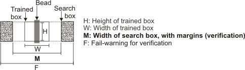
For example, if the width of the trained box is 100 pixels, the trained nominal width of the bead is 60 pixels, and the additional width for the search box is 50%, the search box width is 130 pixels (100 + (60 x 0.5). In this case, the search box is 30 pixels wider (15 pixels on each if its sides) than the trained box. INQ (summarize)Sets an additional width for the search box MIL uses to verify the template's measured bead. INQ (more details...) |
|||||||||||||||||||||||||||||||||||||||
|
Specifies the default value; the default value is 50.0%. |
|||||||||||||||||||||||||||||||||||||||
|
Specifies the additional width used for verification, as a percentage. |
|||||||||||||||||||||||||||||||||||||||
|
Sets an additional width to the search box in which a measured point can be found, but will have a failed status result (M_STATUS). When measured points fall outside the search box, but within this additional width, you can still retrieve results about them, such as their found position. If M_FAIL_WARNING_OFFSET is less than the search box width that MIL uses for validating measured points (M_BOX_WIDTH_MARGIN), M_FAIL_WARNING_OFFSET has no effect. INQ 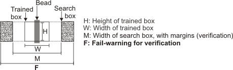
Sets an additional width to the search box in which a measured point can be found, but will have a failed status result (M_STATUS). INQ (more details...) |
|||||||||||||||||||||||||||||||||||||||
|
Specifies the default value; the default value is 0.0. |
|||||||||||||||||||||||||||||||||||||||
|
Specifies the width, relative to the input coordinate system specified using M_TEMPLATE_INPUT_UNITS. |
|||||||||||||||||||||||||||||||||||||||
|
Sets the maximum allowable length of one single gap in the template's measured bead, for it to have a passing status result (M_STATUS). A gap refers to a section of the measured bead that corresponds to a single trained point, or to a set of consecutive trained points, that were expected but not found during verification. If any gap is longer than M_GAP_MAX_LENGTH, the template's measured bead will not have a passing status, regardless of any other setting. INQ (summarize)Sets the maximum allowable length of one single gap in the template's measured bead, for it to have a passing status result (M_STATUS). INQ (more details...) |
|||||||||||||||||||||||||||||||||||||||
|
Specifies the default value; the default value is 0.0. |
|||||||||||||||||||||||||||||||||||||||
|
Specifies that M_GAP_MAX_LENGTH has no effect. |
|||||||||||||||||||||||||||||||||||||||
|
Specifies the maximum gap length, relative to the input coordinate system specified using M_TEMPLATE_INPUT_UNITS. A value of 0.0 indicates that no gaps are allowed. (summarize)Specifies the maximum gap length, relative to the input coordinate system specified using M_TEMPLATE_INPUT_UNITS. (more details...) |
|||||||||||||||||||||||||||||||||||||||
|
Sets the percentage of the total allowable gap (all gaps together) in the template's measured bead, for it to have a passing status result (M_STATUS). A gap refers to a section of the measured bead that corresponds to a single trained point, or to a set of consecutive trained points, that were expected but not found during verification. If the total combined length of all gaps in the measured bead, relative to the full length of the corresponding bead template, is greater than M_GAP_TOLERANCE, the template's measured bead will not have a passing status, regardless of any other setting. INQ (summarize)Sets the percentage of the total allowable gap (all gaps together) in the template's measured bead, for it to have a passing status result (M_STATUS). INQ (more details...) |
|||||||||||||||||||||||||||||||||||||||
|
Specifies the default value; the default value is 0.0%. |
|||||||||||||||||||||||||||||||||||||||
|
Specifies the total allowable gaps, as a percentage. A value of 0.0% indicates that no gaps are allowed. (summarize)Specifies the total allowable gaps, as a percentage. (more details...) |
|||||||||||||||||||||||||||||||||||||||
|
Sets the lowest pixel intensity that is considered valid for the measured bead, relative to the nominal intensity. That is, LowestValidIntensity = NominalIntensity - M_INTENSITY_DELTA_NEG. The nominal intensity can either be established by the training phase (M_INTENSITY_NOMINAL_MODE set to M_AUTO) or with an explicit value (M_INTENSITY_NOMINAL). You can only use this value with stripe-beads. INQ (summarize)Sets the lowest pixel intensity that is considered valid for the measured bead, relative to the nominal intensity. INQ (more details...) |
|||||||||||||||||||||||||||||||||||||||
|
Specifies the default value; the default value is 0.0. |
|||||||||||||||||||||||||||||||||||||||
|
Specifies the lowest valid pixel intensity. |
|||||||||||||||||||||||||||||||||||||||
|
Sets the highest pixel intensity that is considered valid for the measured bead, relative to the nominal intensity. That is, HighestValidIntensity = NominalIntensity + M_INTENSITY_DELTA_POS. The nominal intensity can either be established by the training phase (M_INTENSITY_NOMINAL_MODE set to M_AUTO) or with an explicit value (M_INTENSITY_NOMINAL). You can only use this value with stripe-beads. INQ (summarize)Sets the highest pixel intensity that is considered valid for the measured bead, relative to the nominal intensity. INQ (more details...) |
|||||||||||||||||||||||||||||||||||||||
|
Specifies the default value; the default value is 0.0. |
|||||||||||||||||||||||||||||||||||||||
|
Specifies the highest valid pixel intensity. |
|||||||||||||||||||||||||||||||||||||||
|
Sets the nominal pixel intensity of the template's measured bead. M_INTENSITY_NOMINAL only has an effect if you set M_INTENSITY_NOMINAL_MODE to M_USER_DEFINED. To specify a range of acceptable pixel-intensities for the measured bead, use M_INTENSITY_DELTA_NEG and M_INTENSITY_DELTA_POS. You can only use this value with stripe-beads. INQ (summarize)Sets the nominal pixel intensity of the template's measured bead. INQ (more details...) |
|||||||||||||||||||||||||||||||||||||||
|
Specifies the default value; the default value is 0.0. |
|||||||||||||||||||||||||||||||||||||||
|
Specifies the nominal pixel intensity. |
|||||||||||||||||||||||||||||||||||||||
|
Sets the maximum allowable distance between the position of the trained points in the template, and the position of the corresponding measured points in the target, for the measured bead to have a passing status result (M_STATUS). Measured points must always fall within the search box (for example, M_BOX_WIDTH_MARGIN). INQ (summarize)Sets the maximum allowable distance between the position of the trained points in the template, and the position of the corresponding measured points in the target, for the measured bead to have a passing status result (M_STATUS). INQ (more details...) |
|||||||||||||||||||||||||||||||||||||||
|
Same as M_DISABLE. |
|||||||||||||||||||||||||||||||||||||||
|
Specifies that M_OFFSET_MAX has no effect. |
|||||||||||||||||||||||||||||||||||||||
|
Specifies the allowable offset, relative to the input coordinate system specified using M_TEMPLATE_INPUT_UNITS. |
|||||||||||||||||||||||||||||||||||||||
|
Sets the valid delta negative tolerance between the width of the measured bead and the nominal width of the corresponding template, for the measured bead to have a passing status result (M_STATUS). You can only use this value with stripe-beads. INQ (summarize)Sets the valid delta negative tolerance between the width of the measured bead and the nominal width of the corresponding template, for the measured bead to have a passing status result (M_STATUS). INQ (more details...) |
|||||||||||||||||||||||||||||||||||||||
|
Same as M_DISABLE. |
|||||||||||||||||||||||||||||||||||||||
|
Specifies that M_WIDTH_DELTA_NEG has no effect. |
|||||||||||||||||||||||||||||||||||||||
|
Specifies the tolerance, relative to the input coordinate system specified using M_TEMPLATE_INPUT_UNITS. |
|||||||||||||||||||||||||||||||||||||||
|
Sets the valid delta positive tolerance between the width of the measured bead and the nominal width of the corresponding template, for the measured bead to have a passing status result (M_STATUS). You can only use this value with stripe-beads. INQ (summarize)Sets the valid delta positive tolerance between the width of the measured bead and the nominal width of the corresponding template, for the measured bead to have a passing status result (M_STATUS). INQ (more details...) |
|||||||||||||||||||||||||||||||||||||||
|
Same as M_DISABLE. |
|||||||||||||||||||||||||||||||||||||||
|
Specifies that M_WIDTH_DELTA_POS has no effect. |
|||||||||||||||||||||||||||||||||||||||
|
Specifies the tolerance, relative to the input coordinate system specified using M_TEMPLATE_INPUT_UNITS. |
|||||||||||||||||||||||||||||||||||||||
The following ControlType and corresponding ControlValue parameter settings are used to control how MIL performs the edge extraction of the bead from the training (MbeadTrain()) and target (MbeadVerify()) image. In this case, you must set the LabelOrIndex parameter to a specific template (M_TEMPLATE_INDEX() or M_TEMPLATE_LABEL()) or to all templates (M_ALL).
MIL extracts beads from images using processes based on the MIL Measurement module. Such processes use a one-dimensional analysis of differences in pixel intensities. For more information about this type of edge extraction, see the Search algorithm section of Chapter 16: Measurement.
|
To control how MIL extracts beads from an image for
the training and verification phases
|
|||||||||||||||||||||||||||||||||||||||
|
|
Description | ||||||||||||||||||||||||||||||||||||||
| ControlValue | |||||||||||||||||||||||||||||||||||||||
|
Sets whether the foreground that MIL uses when performing the edge extraction of the bead from an image should be darker or lighter than the background. Only beads with the specified foreground will be trained or verified, depending on which function you are calling. INQ (summarize)Sets whether the foreground that MIL uses when performing the edge extraction of the bead from an image should be darker or lighter than the background. INQ (more details...) |
|||||||||||||||||||||||||||||||||||||||
|
Same as M_FOREGROUND_WHITE. |
|||||||||||||||||||||||||||||||||||||||
|
Specifies that the foreground is darker than the background. For example, a black bead on a white surface. (summarize)Specifies that the foreground is darker than the background. (more details...) |
|||||||||||||||||||||||||||||||||||||||
|
Specifies that the foreground is lighter than the background. For example, a white bead on a black surface. (summarize)Specifies that the foreground is lighter than the background. (more details...) |
|||||||||||||||||||||||||||||||||||||||
|
Sets the degree of noise reduction that MIL uses when performing the edge extraction of the bead from an image. INQ (summarize)Sets the degree of noise reduction that MIL uses when performing the edge extraction of the bead from an image. INQ (more details...) |
|||||||||||||||||||||||||||||||||||||||
|
Specifies the default value; the default value is 50.0. |
|||||||||||||||||||||||||||||||||||||||
|
Specifies the smoothness value. A setting of 0.0 indicates almost no noise reduction effect, while a setting of 100.0 indicates a very strong noise reduction effect. (summarize)Specifies the smoothness value. (more details...) |
|||||||||||||||||||||||||||||||||||||||
|
Sets how to establish the threshold that MIL must use when performing the edge extraction of the bead from an image. INQ (summarize)Sets how to establish the threshold that MIL must use when performing the edge extraction of the bead from an image. INQ (more details...) |
|||||||||||||||||||||||||||||||||||||||
|
Same as M_USER_DEFINED. |
|||||||||||||||||||||||||||||||||||||||
|
Specifies that the threshold is explicitly defined with M_THRESHOLD_VALUE. |
|||||||||||||||||||||||||||||||||||||||
|
Sets the value beneath which a grayscale variation within the image is not considered an edge of the bead. This value only applies if M_THRESHOLD_MODE is set to M_USER_DEFINED. INQ (summarize)Sets the value beneath which a grayscale variation within the image is not considered an edge of the bead. INQ (more details...) |
|||||||||||||||||||||||||||||||||||||||
|
Specifies the default value; the default value is 10.0. |
|||||||||||||||||||||||||||||||||||||||
|
Specifies the threshold value. To consider all grayscale variations as possible edges of the bead, irrespective of their grayscale value, set M_THRESHOLD_VALUE to 0.0. However, in this case, due to the increased number of edges, processing time might increase, and false positives might occur. (summarize)Specifies the threshold value. (more details...) |
|||||||||||||||||||||||||||||||||||||||
The following ControlType and corresponding ControlValue parameter settings are used to associate a camera calibration context with the training image. In this case, you must set the LabelOrIndex parameter to M_CONTEXT.
|
To associate a camera calibration context with a
training image
|
|||||||||||||||||||||||||||||||||||||||
|
|
Description | ||||||||||||||||||||||||||||||||||||||
| ControlValue | |||||||||||||||||||||||||||||||||||||||
|
Associates the specified camera calibration context with the training image specified in MbeadTrain(), if required. MIL requires a calibrated training image if your training settings are specified in world units (M_TEMPLATE_INPUT_UNITS and/or M_TRAINING_BOX_INPUT_UNITS set to M_WORLD). If you associate a camera calibration, and you pass a calibrated training image to MbeadTrain(), MIL ignores the associated camera calibration (M_ASSOCIATED_CALIBRATION), and uses the image's camera calibration instead. Note that if you do not save the camera calibration context with the bead context (MbeadSave() or MbeadStream() with M_WITH_CALIBRATION), you must use M_ASSOCIATED_CALIBRATION to re-associate the camera calibration context after restoring the bead context (MbeadRestore() or MbeadStream()). This value is for the training phase (MbeadTrain()). If you modify this value, you must retrain the context before the next verification. INQ (summarize)Associates the specified camera calibration context with the training image specified in MbeadTrain(), if required. INQ (more details...) |
|||||||||||||||||||||||||||||||||||||||
|
Same as M_NULL. |
|||||||||||||||||||||||||||||||||||||||
|
Removes the association between the training image and the camera calibration context. |
|||||||||||||||||||||||||||||||||||||||
|
Specifies the camera calibration context to associate with the training image. |
|||||||||||||||||||||||||||||||||||||||
The following ControlType and corresponding ControlValue parameter settings are used to control operations with MbeadGetNeighbors(). In this case, you must set the LabelOrIndex parameter to M_CONTEXT.
|
To control operations with
MbeadGetNeighbors()
|
|||||||||||||||||||||||||||||||||||||||
|
|
Description | ||||||||||||||||||||||||||||||||||||||
| ControlValue | |||||||||||||||||||||||||||||||||||||||
|
Sets the maximum distance for the M_CLOSEST_... operations in MbeadGetNeighbors(). INQ (summarize)Sets the maximum distance for the M_CLOSEST_... operations in MbeadGetNeighbors(). INQ (more details...) |
|||||||||||||||||||||||||||||||||||||||
|
Same as M_INFINITE. |
|||||||||||||||||||||||||||||||||||||||
|
Specifies that the maximum distance is infinite. |
|||||||||||||||||||||||||||||||||||||||
|
Specifies the maximum distance, relative to the input coordinate system specified using M_TEMPLATE_INPUT_UNITS. |
|||||||||||||||||||||||||||||||||||||||
|
void MbeadControlInt64
(MIL_ID ContextBeadId,
MIL_INT LabelOrIndex,
MIL_INT64 ControlType,
MIL_INT64 ControlValue)
Parameters
ContextBeadId See ContextBeadId of the main function for a description. LabelOrIndex See LabelOrIndex of the main function for a description. ControlType See ControlType of the main function for a description. ControlValue See ControlValue of the main function for a description. |
|
void MbeadControlDouble
(MIL_ID ContextBeadId,
MIL_INT LabelOrIndex,
MIL_INT64 ControlType,
MIL_DOUBLE ControlValue)
Parameters
ContextBeadId See ContextBeadId of the main function for a description. LabelOrIndex See LabelOrIndex of the main function for a description. ControlType See ControlType of the main function for a description. ControlValue See ControlValue of the main function for a description. |
| Header | Include mil.h. |
| Library | Use mil.lib; milbead.lib. |
| DLL | Requires mil.dll; milbead.dll. |