Defining, training, and modifying bead templates
- See also

 Availability
 Previous
- Next

-
Polyline that you must refine with a training image (M_POLYLINE_SEED).
-
Fixed polyline (M_POLYLINE).
-
Move a template (M_TRANSLATE_POINTS).
-
Rotate a template around its origin (M_ROTATE_POINTS).
-
Resize a template according to a scale factor (M_SCALE_POINTS).
-
Remove a set of vertices from a template (M_DELETE).
-
Add a set of vertices to a template (M_INSERT).
-
Replace a set of vertices in a template with another set of vertices (M_REPLACE).
-
For a template to be completely trained, every trained point that was expected must have been established (found). MIL only returns M_COMPLETE when all templates in the context meet this requirement.
-
For a template to be partially trained, at least two trained points (but less than all) that were expected must have been established (found). MIL only returns M_PARTIAL when one or more templates in the context meet this requirement.
-
For a template to be not-trained, no trained point (or only one) has been established (found). MIL only returns M_NOT_TRAINED when one or more templates in the context meet this requirement. M_NOT_TRAINED can indicate that you have not yet called MbeadTrain().
-
Modifying the template's vertices with MbeadTemplate() to ensure that the template's path follows a polyline that replicates, as accurately as possible, the bead in the training image. To do so, you can try increasing the number or positional accuracy of your vertices.
-
Adjusting the width of the template's path to encompass the width along the entire length of the bead in the training image. Ensure that the width of the path includes the largest possible width of the bead in the training image.
-
Resizing the training box in which MIL finds the trained points. Ensure that the training box includes the largest possible width of the bead. You can also modify the spacing between the training boxes, which essentially alters the number of trained points expected.
-
Improving the quality of the bead in the training image by adjusting the smoothness and threshold settings that MIL uses to extract the bead from the image.
-
Set the bead's type (M_BEAD_STRIPE or M_BEAD_EDGE).
-
Set the bead's path (M_TRAINING_PATH).
-
A polyline that must be refined with a training image (M_POLYLINE_SEED).
-
A fixed polyline (M_POLYLINE).
-
-
Set the width of the bead's path (M_WIDTH_NOMINAL_MODE).
-
Automatically establish the path's width from a training image (M_AUTO_UNIFORM or M_AUTO_CONTINUOUS).
-
For stripe beads, set the range of valid widths (M_TRAINING_WIDTH_NOMINAL, M_TRAINING_WIDTH_SCALE_MAX, and M_TRAINING_WIDTH_SCALE_MIN).
-
-
Explicitly set the path's width value (M_USER_DEFINED).
-
Set the width value (M_WIDTH_NOMINAL).
-
For polyline beads with varying widths, set the width to associate to the specified vertices (M_SET_WIDTH_NOMINAL).
-
-
-
Set the training box (M_TRAINING_BOX_HEIGHT, M_TRAINING_BOX_WIDTH, and M_TRAINING_BOX_SPACING).
-
Train the template (MbeadTrain()).
After allocating a bead context using MbeadAlloc(), you can add bead templates to it using MbeadTemplate().
A bead template is a reusable model of a bead. To define a template, you can specify a variety of settings, such as its type, path, and width. For example, you can define a template that represents a bead stripe, follows a polyline path (according to specified vertices), and has a consistent nominal width. To establish a closed bead template, the first and last points in the path must be at the same position.

Once you have specified the settings of your templates, you must train them using MbeadTrain(). During the training phase, MIL typically uses a training image to refine the template's path (that you initially specified) and establish the template's trained points.

Once trained, a bead template contains all the information required to verify beads, such as the trained points.
Template type
A template's type refers to whether the template represents a bead that is an edge (edge-bead) or a stripe (stripe-bead). Templates that represent an edge indicate that the bead is essentially an outline, which has been delineated by a boundary established from intensity transitions in an image. In general, you should use an edge-bead to represent the skeletal border of an object. Templates that represent a stripe indicate that the bead has two edges separated by a width. In general, you should use a stripe-bead to represent a strip of some malleable material, such as glue or lead. By default, MIL assumes that you are using stripe-beads.


To specify that the template represents a bead that is a stripe or an edge, use MbeadTemplate() with M_BEAD_STRIPE or M_BEAD_EDGE, respectively, when adding the template. Deciding whether your template should represent a stripe or an edge depends on the bead that you will be working with and the requirements of your application.
Foreground
By default, MIL assumes that the foreground of the measured bead is lighter than the background. For stripe-beads, this implies a light stripe-bead (for example, a white bead) on a dark background (for example, a black surface).
To establish the foreground of an edge-bead, MIL considers the bead's direction, which is implied by the order of its vertices. Based on the direction, the foreground is on the left side of the edge-bead, when following the path of the bead in that direction; the background is on the right side.

To set whether MIL considers the foreground to be lighter or darker than the background, use MbeadControl() with M_FOREGROUND_VALUE.
Template path
A template's path represents the continuous sequence of positions that the bead follows. To establish the path of a template, use MbeadControl() with M_TRAINING_PATH. You can specify that the template's path follows a:
All paths are available with templates representing a bead that is either a stripe (M_BEAD_STRIPE) or an edge (M_BEAD_EDGE).
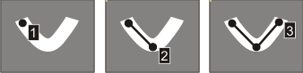
Polyline that will be refined by a training image
By default (M_POLYLINE_SEED), the template's path follows a polyline that you must specify with vertices, and that MIL must refine with a training image. If you use M_POLYLINE_SEED and do not specify a training image when calling MbeadTrain(), you will get an error.
To define the polyline, you must specify the X- and Y-coordinates of its vertices when adding the template using MbeadTemplate() with M_ADD. The order of the vertices establishes the polyline's shape and direction. Typically, you will derive the positions of the vertices from the same image that you will use as your training image (which is usually a good version of a typical target image that you will use in the verification phase). A polyline path must have at least two vertices.

Ideally, each vertex that you add with MbeadTemplate() should be at a position that corresponds to (or, is close to) a point along the corresponding bead in the training image. If there is an acute angle (0° to 90°), you should add a vertex at the angle's corner and on either side of the corner, to ensure that MIL properly establishes the path.
Several operations are available for templates whose path is M_POLYLINE_SEED, such as inserting, removing, and modifying its vertices. For more information, see the General operations with a template subsection of this section.
All templates in a bead context use the same training image. If you require multiple training images to refine the paths your templates must follow, use multiple bead contexts.
Fixed polyline
To specify a polyline path that is fixed, use M_POLYLINE. In this case, the trained position of the path will always follow the specified vertices (the path's position is not refined by a training image, even if you specify one). Typically, you should only use M_POLYLINE when your vertices define the exact path required to train the bead. Such points can, for example, come from a CAD file. To define a fixed polyline, you must specify its vertices using MbeadTemplate() with M_ADD, as explained in the Polyline that will be refined by a training image subsection of this section.
Even when specifying a fixed polyline path, MIL creates trained points along the path by default. In this case, although the trained path will be the same as the path specified by the vertices, the number of trained points in the template will be greater than the number of vertices you specified (which can improve accuracy for the verification phase). If you want the trained points to be exactly the same as the vertices specified, you must disable the spacing control MIL uses to distribute the trained points by setting M_TRAINING_BOX_SPACING to M_DISABLE. For more information, see the Training box of the template subsection of this section.

Fixed circle or segment
To specify a path that follows a fixed circle or segment, use M_CIRCLE or M_SEGMENT. In this case, the trained position of the circle or segment path will always follow the specified path (the path's position is not refined by a training image, even if you specify one).
Unlike paths that follow a polyline, you do not specify vertices to set paths that follow a circle or segment. Instead, once you have added the template with M_ADD, you must define the circle or segment path using MbeadControl() with M_TEMPLATE_CIRCLE_CENTER_X, M_TEMPLATE_CIRCLE_CENTER_Y, and M_TEMPLATE_CIRCLE_RADIUS for circles, or M_TEMPLATE_SEGMENT_START_X, M_TEMPLATE_SEGMENT_START_Y, M_TEMPLATE_SEGMENT_END_X, and M_TEMPLATE_SEGMENT_END_Y for segments.
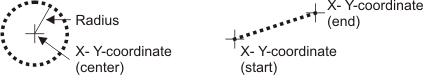
You can consider this as a quick way to create a circle or segment path, without having to provide multiple vertices to the template.
The direction of fixed segments is from their start point to their end point, while the direction of fixed circles is counter-clockwise. MIL uses the direction to establish the bead's foreground. For more information, see the Foreground subsection of this section.
Template from a 2D graphics list
You can add a bead template based on the vertices of a polyline (or polygon) from a 2D graphics list, by calling MbeadTemplate() with M_ADD_FROM_GRAPHIC_LIST. The 2D graphics list must contain one polyline (or polygon) graphic, added with MgraLines() or MgraInteractive(). For more information about interactively adding graphics to a 2D graphics list, see the Creating graphics interactively subsection of the Creating and modifying graphics interactively section of Chapter 24: Generating graphics.
MIL considers the specified vertices (MgraLines() or MgraInteractive()) as the template's vertices. Templates added with M_ADD_FROM_GRAPHIC_LIST behave the same as those added with M_ADD, and whose path is set to M_POLYLINE_SEED (default) or M_POLYLINE. For more information, see the Template path subsection of this section.
Note that a polygon is simply a polyline that MIL automatically closes by connecting the final vertex to the first with a straight line. Any operation or setting in the MIL Bead module that applies to polylines also applies to polygons.
Template width
A template's width refers to how thick its bead is, from side to side, along its path. If a template represents a bead that is a stripe (M_BEAD_STRIPE), the width refers to the thickness between the stripe's two edges. If the template represents a bead that is an edge (M_BEAD_EDGE), the width refers to the thickness of the edge's intensity transition.
To specify how to establish the width of the template's path, use MbeadControl() with M_WIDTH_NOMINAL_MODE. You can either establish the width automatically according to a training image, or you can explicitly set it.
During training, MIL attempts to establish the best possible width (the trained width) using your width settings, and all other relevant template settings. For example, to establish the best trained width, MIL also considers the actual width of the bead in the training image (if one is used). To inquire the actual trained width of the bead template corresponding to each trained point along the bead template's path, use MbeadInquire() with M_TRAINED_INDIVIDUAL_WIDTH_NOMINAL. If the template's path follows a polyline, you can also inquire the width corresponding to each originally-specified vertex (before training), using M_INDIVIDUAL_WIDTH_NOMINAL. To inquire the trained nominal width of the bead template (that is, the average width of the bead template), use M_TRAINED_WIDTH_NOMINAL.
Automatically establishing the width
By default, MIL uses a training image to automatically establish an average width along the specified path (M_AUTO_UNIFORM); in this case, the trained bead width at each trained point is the same. To use a training image to establish a unique width at the position of each trained point, specify M_AUTO_CONTINUOUS. If you use M_AUTO_... and do not specify a training image, you will get an error.

When using M_AUTO_... with a stripe-bead template, you can specify a range of valid bead widths. If the width established by the training phase is bigger or smaller than the specified range, the template will not be trained. To set the range of valid bead widths, you must set a nominal width using MbeadControl() with M_TRAINING_WIDTH_NOMINAL, and an upper and lower factor by which the nominal width can vary, using M_TRAINING_WIDTH_SCALE_MAX and M_TRAINING_WIDTH_SCALE_MIN.
Explicitly setting the width
To define an explicit nominal width for the path, you must set M_WIDTH_NOMINAL_MODE to M_USER_DEFINED, and then use M_WIDTH_NOMINAL to specify the value of the nominal width.
The width set for M_WIDTH_NOMINAL applies to the entire path. If the template's path follows a polyline, you can also specify a unique width value for one or more of its vertices, using MbeadTemplate() with M_SET_WIDTH_NOMINAL. You should only set the width of a vertex when you know that it differs from the nominal width. MIL linearly interpolates the width between consecutive vertices.

Training box of the template
The training box specifies the area along the path in which to establish a trained point when you call MbeadTrain(). To define the training box, you must specify its height (M_TRAINING_BOX_HEIGHT) and width (M_TRAINING_BOX_WIDTH); you must also define the amount of space between the center of each training box along the path (M_TRAINING_BOX_SPACING). The spacing between the boxes affects the total number of trained points (one per box) along the path.

MIL establishes trained points at regular intervals along the template's path and ensures that a trained point is at the start and end of paths that are not closed. The specified spacing is therefore adjusted accordingly, when you call MbeadTrain(). Similarly, MIL also modifies the specified height of the training box to achieve the best value based on all settings and the training image, if you are using one (note that MIL does not typically alter the specified training box width). To inquire the actual (trained) spacing, height, and width that MIL establishes, use MbeadInquire() with M_TRAINED_BOX_SPACING, M_TRAINED_BOX_HEIGHT and M_TRAINED_BOX_WIDTH. To inquire the position and number of trained points, use M_TRAINED_POSITION_X, M_TRAINED_POSITION_Y, and M_TRAINED_SIZE. To inquire the training values exactly as you specified them, use M_TRAINING_....
If your template follows a polyline path that MIL must refine with a training image (M_POLYLINE_SEED), the template can only be completely trained if the trained point expected for each training box is located in the training image.

When using a polyline path that MIL refines with a training image, you should ensure that the training box is large enough to enclose the bead's width, otherwise MIL might not be able to completely train the template. For more information, see the Template width subsection of this section and the Training status subsection of this section.
Smoothness and threshold
When you are using a training image with questionable qualities, such as specular highlights and low contrast, and some expected trained points are not found, or you are finding unwanted points, you might consider modifying the default smoothness (M_SMOOTHNESS) and threshold (M_THRESHOLD_VALUE) settings that MIL uses to extract the bead. In general, the training image should be a good representation of the target images that you will use with MbeadVerify().
Smoothness is the noise reduction that MIL applies when extracting beads from an image. You can set the smoothness to a value between 0.0 (almost no noise reduction) and 100.0 (a very strong noise reduction). The default is 50.0, which is typically sufficient. If you experience shiny specular highlights on the bead causing unwanted points to be extracted, adjusting the smoothness can be useful.
The threshold ranges from 0.0 to 100.0 and refers to the limit beneath which a grayscale variation within the image is not considered a part of the bead. 0.0 indicates that MIL considers all grayscale variations, while 100.0 indicates that MIL only considers the most extreme grayscale variations. The default is 10.0, which is typically sufficient. If your image has very low contrast, adjusting the threshold can be useful.
Note that MIL extracts beads from images using processes based on the MIL Measurement module. For more information about this process, and how to affect it using smoothness and threshold settings, see the Search algorithm section of Chapter 16: Measurement.
General operations with a template
MbeadTemplate() allows you to perform general operations with a template, such as deleting any template in the context (M_DELETE). For templates whose path follows a polyline (M_POLYLINE_SEED or M_POLYLINE), there are also several other general operations available, allowing you to:
After performing one of these operations, you must re-train the template before calling MbeadVerify().
Obtaining the closest template and vertex
MbeadGetNeighbors() allows you to specify a source position, and to retrieve the label of the closest template, and the closest vertex within that template, to that position. You can also use this function to retrieve the closest vertex within a specified template, to the specified position.
To set the maximum distance within which MIL considers a template or vertex to be the closest, use MbeadControl() with M_CLOSEST_POINT_MAX_DISTANCE. By default, there is no maximum distance.
You can only use MbeadGetNeighbors() with templates whose path follows a polyline.
Training status
Once you have specified the required training settings and used MbeadTrain() to train the templates, you should inquire their training status using MbeadInquire() with M_STATUS. The status accounts for all the templates in the context and is based on the difference between the number of trained points established and the number of trained points expected, after the last call to MbeadTrain() (using the most current settings at that time). As previously discussed, a trained point is expected within each training box along the template's path.
The possible values that MIL returns for M_STATUS are:
The following is a list of possible values that MIL returns for M_STATUS, given the specified condition of the templates in the context:
|
A context with ten templates |
Possible values returned by M_STATUS |
|
In every template, MIL established a trained point for each that was expected. |
|
|
In nine of the templates, MIL established a trained point for all that were expected. In one of the templates, MIL established a trained point for all that were expected, except one (for example, it was not found in the training image). |
|
|
In eight of the templates, MIL established a trained point for each that was expected. In one of the templates, MIL established a trained point for each that was expected, except one. In one template, MIL was only able to establish one trained point that was expected. |
When templates are not completely trained
For the most part, templates that are not completely trained use a training image. Typically, such templates follow a polyline path that MIL must refine (M_POLYLINE_SEED). When such templates fail, it usually indicates that one or more points that MIL expects to be trained (given the template's settings) are not found in the training image. To help decipher why a template isn't completely trained, you can perform drawing operations on the template. For example, you can draw a cross at the position of all the trained points in the template that were expected but not found during the training phase. For more information, see the Drawing section later in this chapter.
In general, you should only verify beads with templates that are completely trained. When they are not, you should re-call MbeadTrain() after modifying the relevant training settings discussed in this subsection. For example, you can try:
Templates that you do not train with a training image, such as those that follow a fixed path (M_POLYLINE, M_CIRCLE, M_SEGMENT) and whose width is explicitly set (M_WIDTH_NOMINAL), are less likely to fail training because their settings do not require MbeadTrain() to make significant preprocessing adjustments. For example, the first call to MbeadTrain() will always completely train a template with two or more vertices, whose path follows a fixed polyline, and whose width is user-defined.
Input units
Certain bead values relating to position and dimension (such as M_TRAINING_BOX_SPACING) can be interpreted in either pixel or world units. To set the units, use MbeadControl() with either M_TEMPLATE_INPUT_UNITS or M_TRAINING_BOX_INPUT_UNITS. This essentially establishes the input coordinate system to use.
If you set the input units to M_PIXEL, related values are interpreted in pixel units (pixel coordinate system). If you use calibrated images and specify M_PIXEL, the specified pixel values will be internally converted to world values.
If you set the input units to M_WORLD, related values are interpreted in world units (relative coordinate system). If you do not use calibrated images and specify M_WORLD, an error will be generated.
To use a calibrated training image, you can either pass one to MbeadTrain(), or you can specify the camera calibration context to associate to the training image using MbeadControl() with M_ASSOCIATED_CALIBRATION. If both camera calibrations are available, MIL ignores the camera calibration set with M_ASSOCIATED_CALIBRATION.
To retain the camera calibration when saving (MbeadSave() or MbeadStream()), you must use M_WITH_CALIBRATION. In this case, you must also use M_WITH_CALIBRATION when restoring the context (MbeadRestore() or MbeadStream()). If you do not save/restore the camera calibration, you must re-associate it after restoring the context.
When you use M_WITH_CALIBRATION, the camera calibration is saved or restored in/from the same file as the bead context and cannot be managed independently from the bead context. When the bead context is freed, the camera calibration is automatically freed as well.
For more information, see the Working with real-world units section of Chapter 26: Calibrating your camera setup.
Saving the training image
To store a copy of the training image with the bead context, use MbeadTrain() with M_SAVE_TRAINING_IMAGE. This is required if you want to draw the training image (MbeadDraw()), or if you want to save a training image with the bead context (MbeadSave() or MbeadStream()), and then use it when you restore the context (MbeadRestore() or MbeadStream()).
Summary of the main training settings
As described above, there are numerous settings for training your template. The following represents a global summary of the main settings, and how they interrelate.