Working with real-world units
- See also

 Availability
 Previous
- Next

One of the main advantages of calibration is the ability to work in real-world units, so that locations in your images correspond to real-world locations.
The following table lists the modules that support input and output units in world units, and those that support regions of interest defined in world units, assuming that the image used is associated with a camera calibration context:
|
Module |
World native processing |
World input units |
World output units |
Region of interest |
|
M3dmap |
Y |
Y |
Y |
N |
|
Mbead |
N |
Y |
Y |
N |
|
Mblob |
N |
Y 1 |
Y |
Y |
|
Mcode |
N |
Y |
Y |
Y |
|
Mcol |
N |
N |
N/A |
Y |
|
Mdmr |
N |
N |
Y |
Y |
|
Medge |
Y |
N |
Y |
N |
|
Mgra |
N/A |
Y |
N/A |
N |
|
Mim |
N |
N |
Y |
N |
|
Mmeas |
N |
Y |
Y |
Y |
|
Mmet |
Y |
Y |
Y |
N |
|
Mmod |
Y |
N |
Y |
N |
|
Mocr |
N |
N |
Y |
Y |
|
Mpat |
N |
N |
Y |
Y |
|
Mreg |
N |
N |
N |
N |
|
Mstr |
N |
N |
Y |
Y |
1 Some exceptions.
Getting results in world units
If an image is calibrated, most results obtained from it will be returned in world units by default. When a result is returned in world units, it is returned with respect to the relative coordinate system. If a result can be returned in either world or pixel units, it will be stated in the function description. You can use a module's M...Control() function with M_RESULT_OUTPUT_UNITS to specify that results should be returned in pixel units instead. Note that if you set this control type to M_WORLD but your results are not obtained from a calibrated image, the module's corresponding M...GetResult() function will generate an error when you try to retrieve results.
You can use McalTransformCoordinate(), McalTransformCoordinateList(), or McalTransformCoordinate3dList() to convert coordinates from their pixel to their world values (or vice versa). The latter two functions allow you to convert an entire list of coordinates at once for better efficiency. McalTransformCoordinate3dList() also allows you to convert a coordinate in the relative coordinate system (or any other world coordinate system) to its corresponding value in any other world coordinate system.
You can use McalTransformResult() to convert a specific non-positional result (a length, angle, or area) from its pixel to its world value (or vice versa). Note, however, that this function uses the average pixel size to perform the conversion; results will be more accurate if you first correct the image.
You can use McalTransformResultAtPosition() to convert an angle from its pixel value to its world value or vice versa at a specified position. In the presence of distortion, some results are meaningless when converted from real-world to pixel units unless considered at a specific position in the image. For example, if a Model Finder model appears warped in a target image, but the camera calibration context of the image compensates for this during the model search, the resulting angle is meaningful in the real-world coordinate system, and meaningless in the pixel coordinate system, unless converted at a specific position in the target image. Since McalTransformResultAtPosition() operates on a position, it is not affected by distortion, and can be applied to uncorrected images.
Input settings in world units
The modules that support settings in world units require that you set the working unit to M_WORLD and you use a calibrated image, before they interpret their settings as being in world units. Otherwise, by default, they interpret their settings as being in pixel units, even if a module natively works in world units.
The function and constant to set the input unit depend on the module (see the table below). Some modules have multiple constants to set the input units, so that you can specify some settings in world units and others in pixel units. Note that if you set these constants to M_WORLD but you don't perform the module's operation on a calibrated image (for example, M...Calculate(), M...Read(), or M...Find()), the operation will generate an error.
|
How to set the working units |
Settings that must respect the specified working units |
|
|
Module |
Function and constant |
|
|
3D Reconstruction |
The 3D Reconstruction module has some settings that are always expected in pixels and some that are always expected in world units. |
Depends on setting. |
|
Bead |
Template points and settings (position and dimension). |
|
|
Search box settings in the training phase. |
||
|
Blob |
Condition low and high values passed to MblobSelect(). |
|
|
Code |
||
|
Graphics |
Position and dimension settings when changing a graphic in a 2D graphics list. |
|
|
Position and dimension settings passed to Mgra...() functions. |
||
|
Measurement |
Position and dimension of the search region. |
|
|
Marker reference position. |
||
|
Position, spacing, and angle of a point marker. |
||
|
Metrology |
The Metrology module accepts input values in world units if the image is calibrated, and pixel units otherwise. When using a calibrated image, you cannot specify pixel units. |
Position and dimension settings. |
Angle convention in MIL
When working in pixel units, you define angles with respect to the pixel coordinate system. In this case, positive angles are always interpreted to be counterclockwise with respect to the initial line.
When working in world units, you define angles with respect to the relative coordinate system. In this case, the direction of rotation of the angles depends on the direction of the Y-axis.
Note that since the Y-axis of an image is oriented downwards by default, the angles in MIL are inverted from mathematical convention. In certain cases, you might want to convert angles from MIL convention to mathematical convention: the negative value of an angle in MIL convention is the positive value of the same angle in mathematical convention. For example, 45° in MIL convention is the same as -45° in mathematical convention.
The inverted nature of angles in MIL leads to complications when dealing with trigonometry, specifically the sine function. If you use the sine function with an input angle in the MIL convention, the result of the function will be in MIL convention, inverted from mathematical convention. It is for this reason that, when rotating a point (x, y) around the origin, the 2D rotation matrix that MIL uses is:
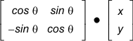
Note that this matrix has already taken into account the inversion of sine functions: the -sin and sin functions are switched from their conventional positions in a standard 2D rotation matrix. Therefore, you don't need to worry about the inverted angles when working with this 2D rotation matrix within MIL.