MmetAddTolerance
- See also

 Availability
 Function map
- Examples
 MmetAddFeature
- MmetAlloc

-
Two segment features.
To validate the angularity between two segment features, MIL internally connects each segment at their start point and considers the angle between them to be, counter-clockwise, from the first segment to the second segment. This angle is valid if it falls within the angular range set by the minimum and maximum tolerance limits. To designate the valid angular range, the minimum and maximum tolerance limits are angles applied counter-clockwise around the start point of the first segment. Note that MIL does not physically rearrange the specified segments, it only orients them internally to measure the required angles.
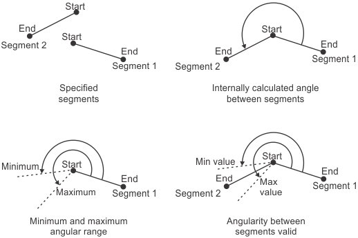
Each segment's start point, as well as the order you list the segments in the FeatureLabelArrayPtr parameter, can affect your results. For example, the angle between segment 1 and segment 2 is different than the angle between segment 2 and segment 1.

-
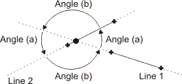
Two line features.
To validate the angularity between two line features, MIL considers the angle between them to be, counter-clockwise, from the first line to the second line. This angle is valid if it falls within the angular range set by the minimum and maximum tolerance limits. To designate the valid angular range, the minimum and maximum tolerance limits are angles applied counter-clockwise, from the first line to the second line, around the intersection point of the two lines.

The order you list the lines in the FeatureLabelArrayPtr parameter can affect your results. For example, the angle between line 1 and line 2 is different than the angle between line 2 and line 1.

Since lines are infinite, there are actually two ways to measure the angle between line 1 and line 2 (indicated as angle (a) in the following diagram) and between line 2 and line 1 (indicated as angle (b) in the following diagram). Note that this is inconsequential since each pair of angles is equivalent.
-
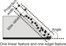
A linear feature (segment or line) and an edgel feature.
For one linear feature (segment or line) and one edgel feature, M_ANGULARITY validates the width of the projection of the edgel feature, along the nominal angle specified using MmetControl() with M_ANGLE. The angle is in the counter-clockwise direction relative to the linear feature. The minimum and maximum tolerance parameters set the valid projection width. Typically, you should set the minimum width value to 0. The width of the projection is in pixel or world units. The second feature specified in the FeatureLabelArrayPtr parameter must be edgel.
-
Three point features.
To validate the angularity between three point features, MIL considers the first point as the center of the angularity tolerance, the second point as the StartAngle (in the counter-clockwise direction relative to the first point), and the third point as the EndAngle (in the counter-clockwise direction relative to the first point). M_ANGULARITY validates the angle that results from EndAngle - StartAngle.

-
Two linear features (segments and lines).
-
A linear feature (segment or line) and an edgel feature.
-
Two linear features (segments and lines).
-
A linear feature (segment or line) and an edgel feature.
- array of type MIL_INT [optionally, in C++: a reference to a
constant std::vector<MIL_INT> ]
(and a maximum array rank for C# of 1)
Required array size:(SizeOfArray) - array of type MIL_INT [optionally, in C++: a reference to a
constant std::vector<MIL_INT> ]
(and a maximum array rank for C# of 1)
Required array size:(SizeOfArray)
in the MIL Reference for the minimum update required.
| MIL_ID ContextId, | //in |
| MIL_INT64 ToleranceType, | //in |
| MIL_INT ToleranceLabel, | //in |
| MIL_DOUBLE ValueMin, | //in |
| MIL_DOUBLE ValueMax, | //in |
| const MIL_INT *FeatureLabelArrayPtr, | //in |
| const MIL_INT *SubFeatureIndexArrayPtr, | //in |
| MIL_INT SizeOfArray, | //in |
| MIL_INT64 ControlFlag | //in |
This function adds a geometric tolerance to the metrology template of the specified metrology context. This function can also modify an existing tolerance of a metrology template. To delete geometric tolerances, use MmetControl() with M_DELETE.
To add several geometric tolerances, you must call this function for each tolerance to add.
A geometric tolerance defines the acceptable deviation from the definition of a feature, or the acceptable relationship between multiple features. For example, you can add a geometric tolerance to the metrology template to specify that one feature must be a certain length, or that two features must be perpendicular. To add a feature, use MmetAddFeature().
When adding a geometric tolerance that requires a point, you can use a specific point subfeature of a measured multiple point feature by specifying its index with the SubFeatureIndexArrayPtr parameter. Note that you cannot do this for other features, including the measured multiple edgel feature, as it is always used as a group.
When adding a geometric tolerance, you must also set its minimum and maximum limit values with the ValueMin and ValueMax parameters. When defining the tolerance of one feature, these limits represent the acceptable deviation from the definition of the feature. For example, a segment's length tolerance can be between 90 and 100 pixels. For multiple features, these limits represent the valid range of acceptable values between the features. For example, the perpendicular tolerance between two segments can be +/- 0.05° (that is, 89.95° to 90.05°). You can also set warning values to alert you when the tolerance is close to its minimum and maximum limits, using MmetControl() with M_VALUE_WARNING_MIN and M_VALUE_WARNING_MAX.
When you call MmetCalculate(), the tolerance is calculated (for example, 95 pixels) and a status is assigned (for example, M_PASS). To retrieve the tolerance value or the status, use MmetGetResult() with M_TOLERANCE_VALUE or M_STATUS, respectively.
You can modify a geometric tolerance (using M_MODIFY) so that it uses a new set of features or subfeatures. In this case, you can also modify the minimum and maximum limit values of a tolerance.
If a camera calibration context is associated with the target image, set values in real-world units (for example, tolerance values and warning values, and positional values). Otherwise use pixel units. For more information, see the Camera calibration - overview section of Chapter 26: Calibrating your camera setup.
Specifies the identifier of the metrology context. The metrology context must have been previously allocated on the required system using MmetAlloc().
Specifies the type of geometric tolerance to add. The icon (image symbol) of every tolerance type is in its description. You can draw this icon using MmetDraw() with M_DRAW_TOLERANCE.
|
For adding geometric tolerances |
|||||||||||||||||||||||||||||||||||||||
| Description | |||||||||||||||||||||||||||||||||||||||
|
Adds an angularity tolerance. The icon for this tolerance is: An angularity tolerance validates that the angle between two features falls within the specified angular range (for example, that two lines intersect at an angle between 25° and 35°). An angularity tolerance can be applied between the following features. Note that an angularity tolerance between a segment and a line produces too many ambiguities and therefore cannot be calculated. (summarize)Adds an angularity tolerance. (more details...) |
|||||||||||||||||||||||||||||||||||||||
|
Adds an area tolerance for the area between two curves of edgels. The icon for this tolerance is: To use M_AREA_BETWEEN_CURVES, you must specify two edgel features (FeatureLabelArrayPtr). MIL internally joins the edgels of each edgel feature to form two curves, between which the area is validated. 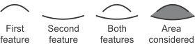
When specifying an edgel feature with this tolerance, MIL internally sorts and filters the edgels, and uses a maximum gap between them, to determine whether they are part of the same curve. To specify an explicit gap size, call MmetControl() with M_CURVE_EDGEL_GAP_SIZE. By default, M_AREA_BETWEEN_CURVES assumes each edgel (curve) feature is unbounded (open), and does not expect the edgels to follow a specific direction. To modify this behavior and potentially speed up calculations and accuracy, call MmetControl() with M_CURVE_INFO. If the two curves cross over each other, there will be areas on both sides of the curves. 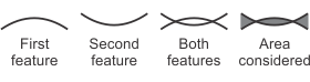
By default, MIL adds all the areas. To modify this behavior (for example, to calculate the area on only one side of a curve), call MmetControl() with M_AREA_BETWEEN_CURVES_ONE_SIDE_ONLY or M_AREA_BETWEEN_CURVES_OPPOSITES_SUBTRACT. If you maintain the default behavior of M_AREA_BETWEEN_CURVES, the order in which you specify the curves is inconsequential. To draw the actual area that MIL uses to define this tolerance, call MmetDraw() with M_DRAW_TOLERANCE_AREA. (summarize)Adds an area tolerance for the area between two curves of edgels. (more details...) |
|||||||||||||||||||||||||||||||||||||||
|
Adds an area tolerance, based on the convex hull, for the surface of an edgel, point, or circle feature. The icon for this tolerance is: M_AREA_CONVEX_HULL validates that the surface area (convex hull) of the specified feature (FeatureLabelArrayPtr) falls within the minimum and maximum limit values. To draw the actual area that MIL uses to define this tolerance, call MmetDraw() with M_DRAW_TOLERANCE_AREA. (summarize)Adds an area tolerance, based on the convex hull, for the surface of an edgel, point, or circle feature. (more details...) |
|||||||||||||||||||||||||||||||||||||||
|
Adds a simple area tolerance for the surface of an edgel, point, or circle feature. The icon for this tolerance is: M_AREA_SIMPLE validates that the surface area of the specified feature (FeatureLabelArrayPtr) falls within the minimum and maximum limit values. To draw the actual area that MIL uses to define this tolerance, call MmetDraw() with M_DRAW_TOLERANCE_AREA. (summarize)Adds a simple area tolerance for the surface of an edgel, point, or circle feature. (more details...) |
|||||||||||||||||||||||||||||||||||||||
|
Adds an area tolerance for the maximum area under a curve of edgels or points. The icon for this tolerance is: M_AREA_UNDER_CURVE_MAX validates the maximum area between a curve (edgel or point) feature and a line feature (FeatureLabelArrayPtr). MIL considers the maximum area to be between an internally established curve under the furthest set of edgels or points and the line. The order of the features specified with the FeatureLabelArrayPtr parameter is inconsequential, since MIL always validates the curve (edgel or point) feature against the line feature. M_AREA_UNDER_CURVE_MAX is typically used to validate the entire area under a curve (edgel or point) feature and a line, regardless of any interfering edges or noise. 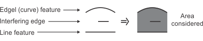
When specifying an edgel feature with this tolerance, MIL internally sorts and filters the edgels, and uses a maximum gap between them, to determine whether they are part of the same curve. To specify an explicit gap size, call MmetControl() with M_CURVE_EDGEL_GAP_SIZE. When specifying a point feature with this tolerance, MIL does not manipulate the points and chains all of them, assuming the resulting curve is well defined; for example, MIL assumes the chained points do not create a degenerate polygonal figure, where curves cross over each other. If the specified curve (edgel or point) feature that you are validating crosses over the specified line feature, you are considered to have opposing areas (that is, there are areas on both sides of the line), and the tolerance fails, by default. You can allow MIL to consider opposing (negative) areas when establishing the area tolerance, by calling MmetControl() with M_AREA_UNDER_CURVE_ALLOW_NEGATIVE. In general, the curve (edgel or point) feature should remain on one side of the line. To draw the actual area that MIL uses to define this tolerance, call MmetDraw() with M_DRAW_TOLERANCE_AREA. (summarize)Adds an area tolerance for the maximum area under a curve of edgels or points. (more details...) |
|||||||||||||||||||||||||||||||||||||||
|
Adds an area tolerance for the minimum area under a curve of edgels. The icon for this tolerance is: M_AREA_UNDER_CURVE_MIN validates the minimum area between a curve (edgel or point) feature and a line feature (FeatureLabelArrayPtr). MIL considers the minimum area to be between an internally established curve under the furthest set of edgels or points and the line. The order of the features specified with the FeatureLabelArrayPtr parameter is inconsequential, since MIL always validates the curve (edgel or point) feature against the line feature. M_AREA_UNDER_CURVE_MIN is typically used to validate the exclusive area under a curve (edgel or point) feature and a line, which excludes the area under the curve and any interfering edges or noise. 
When specifying an edgel feature with this tolerance, MIL performs an internal sort and filtering of the edgels, and uses a maximum gap between edgels to determine whether they are part of the same curve. To specify an explicit gap size, call MmetControl() with M_CURVE_EDGEL_GAP_SIZE. When specifying a point feature with this tolerance, MIL does not manipulate the points and chains all of them, assuming the resulting curve is well defined; for example, MIL assumes the chained points do not create a degenerate polygonal figure, where curves cross over each other. If the specified curve (edgel or point) feature that the tolerance validates crosses over the specified line feature, you are considered to have opposing areas (that is, there are areas on both sides of the line), and the tolerance fails, by default. You can allow MIL to consider opposing (negative) areas when establishing the area tolerance, by calling MmetControl() with M_AREA_UNDER_CURVE_ALLOW_NEGATIVE. In general, the curve (edgel or point) feature should remain on one side of the line. To draw the actual area that MIL uses to define this tolerance, call MmetDraw() with M_DRAW_TOLERANCE_AREA. (summarize)Adds an area tolerance for the minimum area under a curve of edgels. (more details...) |
|||||||||||||||||||||||||||||||||||||||
|
Adds a concentricity tolerance. The icon for this tolerance is: M_CONCENTRICITY validates the concentricity between a combination of two of the following features: arc or circle. This tolerance validates the distance between the centers of the features. Ideally, concentric features have the same center. The order of the features specified in the FeatureLabelArrayPtr parameter is inconsequential. 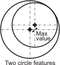
Adds a concentricity tolerance. (more details...) |
|||||||||||||||||||||||||||||||||||||||
|
Adds a maximum distance tolerance. The icon for this tolerance is: M_DISTANCE_MAX validates that a specified maximum distance is separating any two features except lines. By default, MIL uses the distance at which the features are the farthest. In this case, the order of the features in the FeatureLabelArrayPtr parameter is inconsequential. 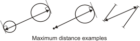
You can explicitly specify an angle at which to apply the maximum distance tolerance between two features, by calling MmetControl() with M_DISTANCE_MODE. This can be seen as a type of caliper tolerance between the features. In this case, the order of the features in the FeatureLabelArrayPtr parameter can affect your results, since MIL considers the specified angle at which to measure the maximum distance to be relative to the first feature. MIL applies the angle counter-clockwise. (summarize)Adds a maximum distance tolerance. (more details...) |
|||||||||||||||||||||||||||||||||||||||
|
Adds a minimum distance tolerance. The icon for this tolerance is: M_DISTANCE_MIN validates that a specified minimum distance is separating any two features. By default, MIL uses the distance at which the features are the closest. In this case, the order of the features in the FeatureLabelArrayPtr parameter is inconsequential. 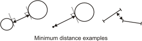
You can explicitly specify an angle at which to apply the minimum distance tolerance between two features, by calling MmetControl() with M_DISTANCE_MODE. This can be seen as a type of caliper tolerance between the features. In this case, the order of the features in the FeatureLabelArrayPtr parameter can affect your results, since MIL considers the specified angle at which to measure the minimum distance to be relative to the first feature. MIL applies the angle counter-clockwise. (summarize)Adds a minimum distance tolerance. (more details...) |
|||||||||||||||||||||||||||||||||||||||
|
Adds a length tolerance. When used with an arc or circle, the icon for this tolerance is: When used with a segment or edgel, the icon for this tolerance is: M_LENGTH validates the length of one of the following features: segment, edgel, circle, or arc. The length of a circle is its circumference. 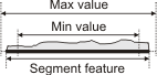
You should only use M_LENGTH with an edgel feature if it represents one continuous curve (path) that does not cross over itself. (summarize)Adds a length tolerance. (more details...) |
|||||||||||||||||||||||||||||||||||||||
|
Adds a parallelism tolerance. The icon for this tolerance is: A parallelism tolerance validates the degree to which two features are parallel. A parallelism tolerance can be applied between the following features: For any combination of 2 linear features (segments and lines), M_PARALLELISM validates that the angle of the two features, relative to the global reference frame, is the same. The minimum and maximum tolerance parameters set the valid angular range, from the nominal angle (0°). In this case, you should only set the maximum tolerance parameter; MIL uses it as both the maximum and minimum value. The order of the features specified in the FeatureLabelArrayPtr parameter, as well as the start/end of the segments, is inconsequential. 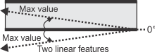
Note that, for parallelism tolerances between two linear features, angles are remapped to 0°; that is, the angle that is measured, and the angular range that you must provide, is the angle that is closest to 0°. 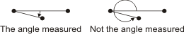
For a linear feature (segment or line) and an edgel feature, M_PARALLELISM validates the width of the projection of the edgel feature on a theoretical line that is perpendicular to the segment or line feature. The minimum and maximum tolerance values set the valid projection width. The smaller the width, the more the edgel feature is parallel to the given segment or line feature. Typically, the minimum width value is set to 0. The width of the projection is in pixel or world units. The second feature specified in the FeatureLabelArrayPtr parameter must be edgel. 
Adds a parallelism tolerance. (more details...) |
|||||||||||||||||||||||||||||||||||||||
|
Adds a perimeter tolerance, based on the convex hull, for the surface of an edgel, point, or circle feature. The icon for this tolerance is: M_PERIMETER_CONVEX_HULL validates that the surface perimeter (convex hull) of the specified feature (FeatureLabelArrayPtr) falls within the minimum and maximum limit values. (summarize)Adds a perimeter tolerance, based on the convex hull, for the surface of an edgel, point, or circle feature. (more details...) |
|||||||||||||||||||||||||||||||||||||||
|
Adds a simple perimeter tolerance for the surface of an edgel, point, or circle feature. The icon for this tolerance is: M_PERIMETER_SIMPLE validates that the surface perimeter of the specified feature (FeatureLabelArrayPtr) falls within the minimum and maximum limit values. (summarize)Adds a simple perimeter tolerance for the surface of an edgel, point, or circle feature. (more details...) |
|||||||||||||||||||||||||||||||||||||||
|
Adds a perpendicularity tolerance. The icon for this tolerance is: A perpendicularity tolerance validates the degree to which two features are perpendicular. A perpendicularity tolerance can be applied between the following features: For any combination of 2 linear features (segments and lines), M_PERPENDICULARITY validates that the angle between the two features is 90°. The minimum and maximum tolerance parameters set the valid angular range, from the nominal angle (90°). The order of the features specified in the FeatureLabelArrayPtr parameter, as well as the start/end of the segments, is inconsequential. 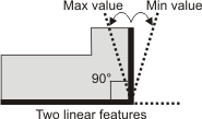
Note that, for perpendicularity tolerances between two linear features, angles are remapped to 90°; that is, the angle that is measured, and the angular range that you must provide, is the angle that is closest to 90°. 
For a linear feature (segment or line) and an edgel feature, M_PERPENDICULARITY validates the width of the projection of the edgel feature on a theoretical line that is parallel to the segment or line feature. The minimum and maximum tolerance values set the valid projection width. The smaller the width, the more the edgel feature is perpendicular to the given segment or line feature. Typically, the minimum width value is set to 0. The width of the projection is in pixel or world units. The second feature specified in the FeatureLabelArrayPtr parameter must be edgel. 
Adds a perpendicularity tolerance. (more details...) |
|||||||||||||||||||||||||||||||||||||||
|
Adds a positioning tolerance, along the X-direction of the specified reference frame. The icon for this tolerance is: A positioning tolerance can be used to validate the geometric relationship between a reference frame and one of the following features: local frame, point, or circle. For a circle feature, only the position of its center is validated, not its contour. If you only specify one feature, MIL validates the geometric relationship between that feature and its reference frame. When using a positioning tolerance, the first element provided to the FeatureLabelArrayPtr parameter must be the label value of the reference frame, while the second element must be the label value of the feature to validate. If you only specify one feature, MIL validates the geometric relationship between that feature and its reference frame (every feature is associated to a reference frame). 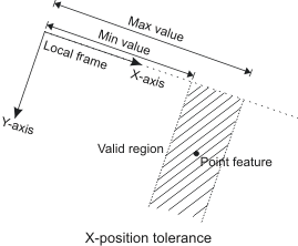
Adds a positioning tolerance, along the X-direction of the specified reference frame. (more details...) |
|||||||||||||||||||||||||||||||||||||||
|
Adds a positioning tolerance, along the Y-direction of the specified reference frame. The icon for this tolerance is: A positioning tolerance can be used to validate the geometric relationship between a reference frame and one of the following features: local frame, point, or circle. For a circle feature, only the position of its center is validated, not its contour. When using a positioning tolerance, the first element provided to the FeatureLabelArrayPtr parameter must be the label value of the reference frame, while the second element must be the label value of the feature to validate. If you only specify one feature, MIL validates the geometric relationship between that feature and its reference frame (every feature is associated to a reference frame). 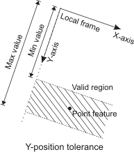
Adds a positioning tolerance, along the Y-direction of the specified reference frame. (more details...) |
|||||||||||||||||||||||||||||||||||||||
|
Adds a radius tolerance. The icon for this tolerance is: M_RADIUS validates the radius of the specified arc or circle feature. The radius is the linear length between the circle or arc's center and perimeter. 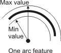
Adds a radius tolerance. (more details...) |
|||||||||||||||||||||||||||||||||||||||
|
Adds a roundness tolerance. The icon for this tolerance is: M_ROUNDNESS validates the roundness of one of the following features: arc, circle, or edgel. MIL establishes a feature's roundness by calculating the distance between the inner and outer circular curves formed by the given feature. Note that the inner and outer curves are concentric. 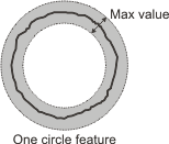
Adds a roundness tolerance. (more details...) |
|||||||||||||||||||||||||||||||||||||||
|
Adds a straightness tolerance. The icon for this tolerance is: M_STRAIGHTNESS validates the straightness of one of the following features: segment or edgel. This is done by calculating the distance between the two parallel lines that are formed by the inner and outer boundaries of the feature. The angle of the two parallel lines is chosen such that the distance between them is the smallest. 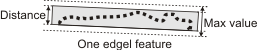
Adds a straightness tolerance. (more details...) |
|||||||||||||||||||||||||||||||||||||||
To modify a geometric tolerance, the ToleranceType parameter can be set to the following value. In this case, you must set the ToleranceLabel parameter to the label of an existing tolerance.
|
For modifying a geometric tolerance |
|||||||||||||||||||||||||||||||||||||||
| Description | |||||||||||||||||||||||||||||||||||||||
|
Modifies the features that the tolerance uses, and the tolerance's minimum and maximum limit values. You cannot modify only the features or only the limits. Use FeatureLabelArrayPtr, SubFeatureIndexArrayPtr, ValueMin, and ValueMax to specify the new features and limits. (summarize)Modifies the features that the tolerance uses, and the tolerance's minimum and maximum limit values. (more details...) |
|||||||||||||||||||||||||||||||||||||||
Specifies the label of the target tolerance.
|
For labeling the tolerance |
|||||||||||||||||||||||||||||||||||||||
| Description | |||||||||||||||||||||||||||||||||||||||
|
Specifies that MIL automatically selects the tolerance's label value. Once a tolerance is added, you can inquire its label using MmetInquire() with the tolerance's index and M_LABEL_VALUE. (summarize)Specifies that MIL automatically selects the tolerance's label value. (more details...) |
|||||||||||||||||||||||||||||||||||||||
|
Specifies the label value. Each tolerance must have a unique label otherwise you will get an error. You can have an extremely high number of labels (up to M_MET_TOLERANCE_ID_MAX). (summarize)Specifies the label value. (more details...) |
|||||||||||||||||||||||||||||||||||||||
Specifies the array that holds the label values of the features whose relationship to validate. The features must have already been added to the metrology template of the metrology context. To add a feature, use MmetAddFeature(). The specified features, whose relationship you want to validate, can be considered the base features of the tolerance.
Specifies the array that holds the index values of the multiple features' subfeatures whose relationship the added tolerance will validate. For non-multiple features (single features), specify 0 as the index. If the tolerance validates the relationship between only single features (there are no multiple features), set SubFeatureIndexArrayPtr to M_NULL.
Specifies the size of the arrays that hold the information that will be used to add the geometric tolerance (FeatureLabelArrayPtr and SubFeatureIndexArrayPtr).
When using a standard vector (std::vector) overload function in C++, you can pass M_DEFAULT to this parameter and MIL will automatically determine the size based on the number of items in the vector passed to the FeatureLabelArrayPtr or SubFeatureIndexArrayPtr parameter.
| Header | Include mil.h. |
| Library | Use mil.lib; milmetrol.lib. |
| DLL | Requires mil.dll; milmetrol.dll. |