|
For controlling features
|
|
|
  M_ACTIVE M_ACTIVE |
Sets whether to enable or disable the feature for
calculation.
(summarize)
Sets whether to enable or disable the feature for
calculation.
(more
details...)
|
|
|
M_DISABLE |
Specifies to disable the feature for calculation. In this case,
the feature is not calculated and the status of the feature
(M_STATUS) will return M_FAIL. This is also the case for the status
of all the derived features and tolerances, if any.
(summarize)
Specifies to disable the feature for
calculation.
(more
details...)
|
|
|
M_ENABLE |
Specifies to enable the feature. This is the default value.
(summarize)
Specifies to enable the feature.
(more
details...)
|
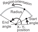
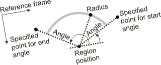
| M_ANGLE_END |
Sets the end angle of a constructed arc. The angle is relative
to the reference frame's X-axis and follows the counter-clockwise
convention. INQ
(summarize)
Sets the end angle of a constructed arc.
INQ
(more
details...)
|
|
|
M_DEFAULT |
Specifies the default value; the default value is 360.0°.
|
|
|
0.0 <= Value <=
360.0 |
Specifies the angle, in degrees.
|
| M_ANGLE_START |
Sets the start angle of a constructed arc. The angle is relative
to the reference frame's X-axis and follows the counter-clockwise
convention. INQ
(summarize)
Sets the start angle of a constructed arc.
INQ
(more
details...)
|
|
|
M_DEFAULT |
Specifies the default value; the default value is 0.0°.
|
|
|
0.0 <= Value <=
360.0 |
Specifies the angle, in degrees.
|
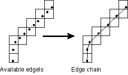
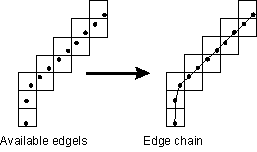
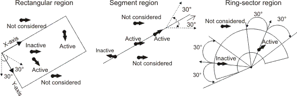
| M_EDGEL_ANGLE_RANGE |
Sets the angular range within which an edgel's gradient angle
must fall for MIL to consider it an active edgel. Active edgels
apply to physically measured features and constructed features
based on physically measured edgels or based on external edgels.
Note that this control type is ignored for points (edgels with no
angle information) in an external edgel feature.
By default, MIL measures the specified angular range, in the
counter clockwise direction, relative to the metrology ROI's
orientation. To change the relative angle from which to measure the
angular range, use M_EDGEL_RELATIVE_ANGLE.
In the following examples, the angular range is 60.0° and the
relative angle is the same as the region's orientation. Note that
for the ring-sector region, the orientation is radial.
Note that constructed edgel features are not built from a
region, but from a specified measured feature. Therefore in this
case, the region's orientation refers to the orientation of the
region from which its specified measured feature was built.
INQ
(summarize)
Sets the angular range within which an edgel's
gradient angle must fall for MIL to consider it an active edgel.
INQ
(more
details...)
|
|
|
M_DEFAULT |
Specifies the default value; the default value is 180.0°.
|
|
|
0.0 <= Value <=
360.0 |
Specifies the angular range, in degrees.
|
| M_EDGEL_DENOISING_MODE |
Sets how to denoise edgels. Denoising refers to establishing and
eliminating noisy (unwanted) edgels.
This setting applies to all physically measured features and
constructed edgel features. INQ
(summarize)
Sets how to denoise edgels. INQ
(more
details...)
|
|
|
M_DEFAULT |
Same as M_NULL.
|
|
|
M_NULL |
Specifies no denoising.
|
|
|
M_GAUSSIAN |
Specifies a Gaussian type of denoising.
|
|
|
M_MEAN |
Specifies a mean type of denoising.
|
|
|
M_MEDIAN |
Specifies a median type of denoising.
|
| M_EDGEL_DENOISING_RADIUS |
Sets the radius by which to denoise edgels.
This setting only has an effect if M_EDGEL_DENOISING_MODE is set to a value
other than its default (which is M_NULL).
This setting applies to all physically measured features and
constructed edgel features. INQ
(summarize)
Sets the radius by which to denoise edgels.
INQ
(more
details...)
|
|
|
M_DEFAULT |
Specifies the default value; the default value is 10.0.
|
|
|
Value >
0.0 |
Specifies the radius, in pixels.
|
| M_EDGEL_DENOISING_USE_ORDER |
Sets whether MIL should use and maintain the order of the edgels
when denoising them.
This setting only has an effect if M_EDGEL_DENOISING_MODE is set to a value
other than its default (which is M_NULL).
This setting applies to all physically measured features and
constructed edgel features. INQ
(summarize)
Sets whether MIL should use and maintain the order
of the edgels when denoising them. INQ
(more
details...)
|
|
|
M_DISABLE |
Specifies that MIL should not use and maintain the order of the
edgels when denoising them.
|
|
|
M_ENABLE |
Specifies that MIL should use and maintain the order of the
edgels when denoising them. This can improve the speed and accuracy
of the denoising. This also ensures that the denoising itself does
not reorder the edgels; keeping the original order can be useful
for future operations.
This is the default value.
(summarize)
Specifies that MIL should use and maintain the order
of the edgels when denoising them.
(more
details...)
|
| M_EDGEL_RELATIVE_ANGLE |
Sets the relative angle from which to measure the gradient angle
range (M_EDGEL_ANGLE_RANGE). You can use M_EDGEL_RELATIVE_ANGLE, along with M_EDGEL_ANGLE_RANGE, to select the active edgels
of a physically measured feature or the active edgels of a
constructed feature based on physically measured edgels or based on
external edgels. Typically, the relative angle is the same as the
region's orientation. For an example on how M_EDGEL_RELATIVE_ANGLE is applied, along
with the gradient angle range, see M_EDGEL_ANGLE_RANGE. Note that this control type
is ignored for points (edgels with no angle information) in an
external edgel feature.
Note that constructed edgel features are not built from a
region, but from a specified measured feature. Therefore in this
case, the region's orientation refers to the orientation of the
region from which its specified measured feature was built.
INQ
(summarize)
Sets the relative angle from which to measure the
gradient angle range (M_EDGEL_ANGLE_RANGE). INQ
(more
details...)
|
|
|
M_DEFAULT |
Same as M_SAME.
|
|
|
M_REVERSE |
Specifies that the gradient angle range is measured relative to
the reverse angle (orientation) of the region of interest (+
180°).
|
|
|
M_SAME |
Specifies that the gradient angle range is measured relative to
the same angle (orientation) as the region of interest.
|
|
|
M_SAME_OR_REVERSE |
Specifies that the gradient angle range is measured relative to
either the same or the reverse angle (orientation) of the region of
interest.
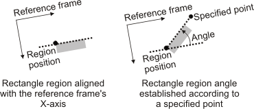
|
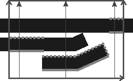
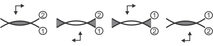
| M_EDGEL_SELECTION_RANK |
Sets the edgels to select relative to the orientation of the
metrology region. The metrology region is scanned column by column,
and the specified edgel encountered within a column is selected.
Note that this control type takes effect after M_EDGEL_RELATIVE_ANGLE and M_EDGEL_ANGLE_RANGE are satisfied. M_EDGEL_SELECTION_RANK applies to M_RECTANGLE derived metrology regions.
In the following example, there are multiple edges in the
metrology region. The solid gray line illustrates the edgels
selected when M_EDGEL_SELECTION_RANK is set to 1; the
dotted gray line illustrates the edgels selected when M_EDGEL_SELECTION_RANK is set to 2.
INQ
(summarize)
Sets the edgels to select relative to the
orientation of the metrology region. INQ
(more
details...)
|
|
|
M_DEFAULT |
Same as M_DISABLE.
|
|
|
M_DISABLE |
Specifies that all edgels are selected.
|
|
|
M_LAST |
Selects the last edgel in each column, relative to the metrology
region.
|
|
|
Value > 0 |
Specifies which edgels to select, based on their rank, relative
to the metrology region.
|
| M_EDGEL_TYPE |
|
|
|
M_DEFAULT |
Same as M_ACTIVE_EDGELS.
|
|
|
M_ACTIVE_EDGELS |
Specifies to use the active edgels of the measured
feature's metrology region.
(more
details...)
|
|
|
M_ALL_EDGELS |
Specifies to use all the edgels of the measured feature's
metrology region.
|
|
|
M_FITTED_EDGELS |
Specifies to use the fitted edgels of the measured feature's
metrology region. The fitted edgels are those active edgels used by
the fit operation to define a measured feature. Fitted edgels must
satisfy all edgel constraints (M_EDGEL_ANGLE_RANGE and M_EDGEL_RELATIVE_ANGLE) and fit constraints
(M_FIT_...).
(summarize)
Specifies to use the fitted edgels of the measured
feature's metrology region.
(more
details...)
|
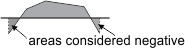
| M_FIT_COVERAGE_MIN |
Sets the approximate portion of the feature that must be covered
by fitted edgels. In the following example, about 50.0% of the
segment feature covers the edgels.
The actual coverage that results from this setting depends on
the scale of the image at which the feature edges were extracted,
as specified with M_EXTRACTION_SCALE; a scale of 1 provides the
best estimation.
M_FIT_COVERAGE_MIN is valid for all fit
operations for physically measured or constructed features. For
constructed features using a fit operation performed on multiple
physically measured edgel features, the accuracy of the minimum fit
coverage is based on the average of each feature's extraction
scale.
This setting can alter the precision of the edge that is
ultimately fit; however, it might not reliably discard outliers
(outlier pixels/points) when they significantly impact the initial
fit (the first iteration of the fit). When dealing with a lot of
outliers, use a robust best fit (M_ROBUST_FIT). INQ
(summarize)
Sets the approximate portion of the feature that
must be covered by fitted edgels. INQ
(more
details...)
|
|
|
M_DEFAULT |
Specifies the default value; the default value is 0.0%.
|
|
|
0.0 <= Value <=
100.0 |
Specifies the minimum coverage, as a percentage.
|
| M_FIT_DISTANCE_MAX |
Sets the greatest possible gap between an active edgel and an
iterative fit for the edgel to be considered during the next
iteration. The higher the value, the farther away an active edgel
can be. M_FIT_DISTANCE_MAX is valid for all fit
operations for physically measured or constructed features.
This setting can alter the precision of the edge that is
ultimately fit; however, it might not reliably discard outliers
(outlier pixels/points) when they significantly impact the initial
fit (the first iteration of the fit). When dealing with a lot of
outliers, use a robust best fit (M_ROBUST_FIT). INQ
(summarize)
Sets the greatest possible gap between an active
edgel and an iterative fit for the edgel to be considered during
the next iteration. INQ
(more
details...)
|
|
|
M_DEFAULT |
Same as M_INFINITE.
|
|
|
M_INFINITE |
Specifies no maximum distance.
|
|
|
Value |
Specifies the maximum distance, in pixel units.
|
| M_FIT_DISTANCE_OUTLIERS |
Sets the distance MIL uses to establish outliers (outlier
pixels/points), which are excluded from the robust best fit. This
only applies to features built using MmetAddFeature() with M_FIT; also, M_FIT_TYPE must be set to M_ROBUST_FIT. INQ
(summarize)
Sets the distance MIL uses to establish outliers
(outlier pixels/points), which are excluded from the robust best
fit. INQ
(more
details...)
|
|
|
M_DEFAULT |
Same as M_AUTO.
|
|
|
M_AUTO |
Specifies that MIL automatically determines the distance.
|
|
|
M_USER_DEFINED |
Specifies that the distance is set with M_FIT_DISTANCE_OUTLIERS_VALUE.
|
| M_FIT_DISTANCE_OUTLIERS_VALUE |
Sets an explicit distance value that MIL uses to
establish outliers (outlier pixels/points), which are excluded from
the robust best fit. INQ
(more
details...)
|
|
|
M_DEFAULT |
Specifies the default value; the default value is 4.0.
|
|
|
Value |
Specifies the distance; value must be greater than 0.0.
|
| M_FIT_INTERNAL_NUMBER_OF_POINTS |
Sets the minimum number of points from which MIL performs the
robust fit to build the feature. This only applies to features
built using MmetAddFeature() with M_FIT; also, M_FIT_TYPE must be set to M_ROBUST_FIT. INQ
(summarize)
Sets the minimum number of points from which MIL
performs the robust fit to build the feature. INQ
(more
details...)
|
|
|
M_DEFAULT |
Same as M_AUTO.
|
|
|
M_AUTO |
Specifies that MIL automatically determines the number of
points. For a segment, MIL uses 2 points. For a circle or arc, MIL
uses 3.
(summarize)
Specifies that MIL automatically determines the
number of points.
(more
details...)
|
|
|
Value |
Specifies the number of points. Less points typically result in
faster fit calculations. For a segment, there is a 2 point minimum,
and for a circle or arc, there is a 3 point minimum.
(summarize)
Specifies the number of points.
(more
details...)
|
| M_FIT_ITERATIONS_MAX |
Sets the maximum number of fit iterations used to compute the
feature. The more iterations, the better the fit, but the slower
the calculation. M_FIT_ITERATIONS_MAX is valid for all fit
operations for physically measured or constructed features.
This setting can alter the precision of the edge that is
ultimately fit; however, it might not reliably discard outliers
(outlier pixels/points) when they significantly impact the initial
fit (the first iteration of the fit). When dealing with a lot of
outliers, use a robust best fit (M_ROBUST_FIT). INQ
(summarize)
Sets the maximum number of fit iterations used to
compute the feature. INQ
(more
details...)
|
|
|
M_DEFAULT |
Same as M_AUTO.
|
|
|
M_AUTO |
Specifies that the maximum number of fit iterations will be
automatically determined.
|
|
|
Value >= 1 |
Specifies the maximum number of fit iterations. Only integer
values are accepted. A setting of one will consider all
edgels/points in the fit. Settings higher than one will
progressively eliminate outlying edgels (outlier pixels/points) in
the fit.
You can only specify a maximum number of fit iterations when
M_FIT_TYPE is set to M_STANDARD_FIT.
(summarize)
Specifies the maximum number of fit iterations.
(more
details...)
|
| M_FIT_TYPE |
Sets the type of best fit with which to build the feature. This
only applies to features built using MmetAddFeature() with M_FIT. INQ
(summarize)
Sets the type of best fit with which to build the
feature. INQ
(more
details...)
|
|
|
M_DEFAULT |
Same as M_STANDARD_FIT.
|
|
|
M_ROBUST_FIT |
Specifies a robust best fit.
(more
details...)
|
|
|
M_STANDARD_FIT |
Specifies a standard best fit. In this case, more importance is
typically given to the edgels whose gradient orientation follows
the region's orientation. However, when adding a segment feature in
an M_INFINITE metrology region with an
M_RADIAL orientation, or in an M_RING_SECTOR metrology region, more
importance is given to the edgels whose gradient orientation is
more perpendicular to the radial direction.
(summarize)
Specifies a standard best fit.
(more
details...)
|
| M_FIT_VARIATION_MAX |
Sets the maximum allowable difference in the value of the
feature's underlying coefficients, from one fit iteration to the
next. If at least one coefficient of the feature varies more,
between two consecutive fit iterations, than the specified value,
the iteration process will continue. Note that:
-
An arc feature has 5 coefficients: the X-coordinate of its
center, the Y-coordinate of its center, its radius, its start
angle, and its end angle.
-
A circle feature has 3 coefficients: the X-coordinate of its
center, the Y-coordinate of its center and its radius.
-
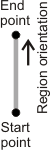
A segment feature has 4 coefficients: the X-coordinate of its
start point, the Y-coordinate of its start point, the X-coordinate
of its end point, and the Y-coordinate of its end point.
These coefficients are the same as those required when building
the corresponding features with a parametric operation.
M_FIT_VARIATION_MAX is valid for all fit
operations for physically measured or constructed features.
This setting can alter the precision of the edge that is
ultimately fit; however, it might not reliably discard outliers
(outlier pixels/points) when they significantly impact the initial
fit (the first iteration of the fit). When dealing with a lot of
outliers, use a robust best fit (M_ROBUST_FIT). INQ
(summarize)
Sets the maximum allowable difference in the value
of the feature's underlying coefficients, from one fit iteration to
the next. INQ
(more
details...)
|
|
|
M_DEFAULT |
Same as M_AUTO.
|
|
|
M_AUTO |
Specifies that the maximum variation will be determined
automatically.
|
|
|
0.0 <= Value <=
100.0 |
Specifies the maximum variation, as a percentage.
|
| M_LINE_A |
Sets the coefficient A of the line equation for a
parametrically constructed line.
The line equation is: A x +
B y + C = 0.
If you use the default for all coefficients (A = 0,
B = 1, and C = 0), MIL constructs a line that runs
along the X-axis of the reference frame. INQ
(summarize)
Sets the coefficient A of the line equation
for a parametrically constructed line. INQ
(more
details...)
|
|
|
M_DEFAULT |
Specifies the default value; the default value is 0.0.
|
|
|
Value |
Specifies the coefficient's value.
|
| M_LINE_B |
Sets the coefficient B of the line equation for a
parametrically constructed line.
The line equation is: A x +
B y + C = 0.
If you use the default for all coefficients (A = 0,
B = 1, and C = 0), MIL constructs a line that runs
along the X-axis of the reference frame. INQ
(summarize)
Sets the coefficient B of the line equation
for a parametrically constructed line. INQ
(more
details...)
|
|
|
M_DEFAULT |
Specifies the default value; the default value is 1.0.
|
|
|
Value |
Specifies the coefficient's value.
|
| M_LINE_BISECTOR_TYPE |
Sets how to construct a line feature when building it as a
bisector. This only applies when using MmetAddFeature() with M_CONSTRUCTED set to M_LINE and M_BISECTOR, and specifying two lines as the
base features. INQ
(summarize)
Sets how to construct a line feature when building
it as a bisector. INQ
(more
details...)
|
|
|
M_DEFAULT |
Same as
M_FEATURE_ORDER.
|
|
|
M_BIGGEST_ANGLE |
Specifies that the newly constructed line is built at the middle
of the biggest angle formed by the two lines specified as base
features.
|
|
|
M_FEATURE_ORDER |
Specifies that the newly constructed line is built according to
the order in which you specified the two line base features; that
is, at the middle of the angle formed between the first and second
specified lines.
|
|
|
M_SMALLEST_ANGLE |
Specifies that the newly constructed line is built at the middle
of the smallest angle formed by the two lines specified as base
features.
|
| M_LINE_C |
Sets the coefficient C of the line equation for a
parametrically constructed line.
The line equation is: A x +
B y + C = 0.
If you use the default for all coefficients (A = 0,
B = 1, and C = 0), MIL constructs a line that runs
along the X-axis of the reference frame. INQ
(summarize)
Sets the coefficient C of the line equation
for a parametrically constructed line. INQ
(more
details...)
|
|
|
M_DEFAULT |
Specifies the default value; the default value is 0.0.
|
|
|
Value |
Specifies the coefficient's value.
|
| M_NUMBER_MAX |
Sets the maximum number of subfeatures to calculate for a
multiple feature. Note that M_NUMBER_MAX is valid for point features only.
INQ
(summarize)
Sets the maximum number of subfeatures to calculate
for a multiple feature. INQ
(more
details...)
|
|
|
M_DEFAULT |
Specifies the default value; the default value is 1.
|
|
|
Value |
Specifies the maximum number of subfeatures. This value must be
greater than 1 for measured multiple point features.
(summarize)
Specifies the maximum number of subfeatures.
(more
details...)
|
| M_NUMBER_MIN |
Sets the minimum number of subfeatures to calculate for a
multiple feature. Note that M_NUMBER_MIN is valid for point features only.
INQ
(summarize)
Sets the minimum number of subfeatures to calculate
for a multiple feature. INQ
(more
details...)
|
|
|
M_DEFAULT |
Specifies the default value; the default value is 0.
|
|
|
Value >= 0 |
Specifies the minimum number of subfeatures. This value must be
greater than 1 for measured multiple point features.
(summarize)
Specifies the minimum number of subfeatures.
(more
details...)
|
| M_OCCURRENCE |
|
|
|
M_DEFAULT |
Specifies the default value; the default value is 0.
|
|
|
Value >= 0 |
Specifies the index value.
|
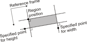
| M_POSITION |
|
|
|
M_DEFAULT |
Specifies the default value; the default value is 0.
|
|
|
Value |
Specifies the position value.
(more
details...)
|
| M_POSITION_END_X |
|
|
|
M_DEFAULT |
Specifies the default value; the default value is 1.0.
|
|
|
Value |
Specifies the X-coordinate, in pixel or world units.
|
| M_POSITION_END_Y |
|
|
|
M_DEFAULT |
Specifies the default value; the default value is 0.0.
|
|
|
Value |
Specifies the Y-coordinate, in pixel or world units.
|
| M_POSITION_START_X |
|
|
|
M_DEFAULT |
Specifies the default value; the default value is -1.0.
|
|
|
Value |
Specifies the X-coordinate, in pixel or world units.
|
| M_POSITION_START_Y |
|
|
|
M_DEFAULT |
Specifies the default value; the default value is 0.0.
|
|
|
Value |
Specifies the Y-coordinate, in pixel or world units.
|
| M_POSITION_X |
Sets the X-coordinate of the center of a constructed circle or
arc, or sets the X-coordinate of a constructed local frame or
point. INQ
(summarize)
Sets the X-coordinate of the center of a constructed
circle or arc, or sets the X-coordinate of a constructed local
frame or point. INQ
(more
details...)
|
|
|
M_DEFAULT |
Specifies the default value; the default value is 0.0.
|
|
|
Value |
Specifies the X-coordinate, in pixel or world units.
|
| M_POSITION_Y |
Sets the Y-coordinate of the center of a constructed circle or
arc, or sets the Y-coordinate of a constructed local frame or
point. INQ
(summarize)
Sets the Y-coordinate of the center of a constructed
circle or arc, or sets the Y-coordinate of a constructed local
frame or point. INQ
(more
details...)
|
|
|
M_DEFAULT |
Specifies the default value; the default value is 0.0.
|
|
|
Value |
Specifies the Y-coordinate, in pixel or world units.
|
| M_RADIUS |
Sets the radius of a constructed circle or arc. INQ
(summarize)
Sets the radius of a constructed circle or arc.
INQ
(more
details...)
|
|
|
M_DEFAULT |
Specifies the default value; the default value is 0.0.
|
|
|
Value >= 0.0 |
Specifies the radius, in pixel or world units.
|
| M_REFERENCE_FRAME |
Sets the feature's reference frame. INQ
(summarize)
Sets the feature's reference frame. INQ
(more
details...)
|
|
|
M_DEFAULT |
Specifies that the reference frame is the global frame.
|
|
|
Value > 0 |
Specifies the label of the reference frame.
|
| M_SORT |
Sets the sorting order that MIL applies to the index of
subpoints, when retrieving results of multiple point features. A
multiple point feature is a point feature that contains more than
one point. By default, the subpoints (points within the point
feature) are sorted in ascending order, from the subpoint with the
lowest index to the subpoint with the highest index. INQ
(summarize)
Sets the sorting order that MIL applies to the index
of subpoints, when retrieving results of multiple point features.
INQ
(more
details...)
|
|
|
M_DEFAULT |
Same as M_SORT_UP.
|
|
|
M_SORT_DOWN |
Specifies that results of multiple point features are sorted in
descending order, according to the subpoint's index.
|
|
|
M_SORT_UP |
Specifies that results of multiple point features are sorted in
ascending order, according to the subpoint's index.
|

 Availability
 Function map