
Filters
Filter values by
- Arc features
- Circle features
- Edgel features
- Line features
- Local frame features
- Point features
- Segment features
 Availability
 Function map
 | MIL_ID ContextId, | //in |
| MIL_INT64 FeatureType, | //in |
| MIL_INT64 Geometry, | //in |
| MIL_INT FeatureLabel, | //in |
| MIL_INT64 BuildOperation, | //in |
| const MIL_INT *FeatureLabelArrayPtr, | //in |
| const MIL_INT *SubFeatureIndexArrayPtr, | //in |
| MIL_INT SizeOfArray, | //in |
| MIL_INT64 ControlFlag | //in |
This function adds a feature to the metrology template of the specified metrology context. This function can also modify an existing feature of a metrology template. To delete features, use MmetControl() with M_DELETE.
To add several features to the template, you must call this function for each feature to add.
Features can either be physically measured from the target image or constructed from a set of other features, which can be referred to as base features. When a feature is composed of several instances of the same feature type, it is considered a multiple feature. Every instance of the feature type is a subfeature of the multiple feature. A single feature is a feature that has only one instance of the feature type. All supported features are single features, except for the edgel feature (M_MEASURED or M_CONSTRUCTED with M_EDGEL) and the measured multiple point feature (M_MEASURED with M_POINT). When adding a constructed feature that requires a point, it is possible to isolate and use a specific point subfeature of a measured multiple point feature. This is not true for the edgel feature since it is always used as a group.
Every feature has a position in the metrology template. For a physically measured feature, its position can be considered to be set according to the metrology region in which it is expected to be established (MmetSetRegion()). By default, the metrology region is infinite (the whole target image). For a constructed feature, its position in the template is defined by the position of the features used to construct it (its base features). The position of a feature is relative to a reference coordinate system, referred to as the reference frame. The global frame is the default. If the target image is not calibrated, the global frame's default origin (0,0) is aligned with the center of the top-left corner pixel of the target image. If the target image is calibrated, the global frame's default origin is aligned with the origin of the relative (world) coordinate system. To change the reference frame to a local frame, use MmetControl() with M_REFERENCE_FRAME. Local frames are coordinate systems located anywhere within the metrology template and defined as metrology features.
Once a feature is added to the template, it is possible to change its position using MmetSetPosition(). In addition, you can modify the feature so that it is constructed from a new set of base features and/or a new build operation; to do so, call MmetAddFeature() with M_MODIFY. Note that you cannot modify a feature's geometry.
To define the acceptable geometric relationship between several features in the template or the acceptable deviation from the definition of a feature, add a geometric tolerance, using MmetAddTolerance(). To calculate the added features and validate the geometric tolerances in the target image, use MmetCalculate(). To change the settings of a feature in the template, use MmetControl().
When adding a constructed feature with a fit operation, or when adding a constructed edgel feature with the clone operation, you can specify base features that have a delimited metrology region (MmetSetRegion()). By default, MIL uses an infinite metrology region (M_INFINITE).
Specifies the identifier of the metrology context containing the template. The metrology context must have been previously allocated on the required system using MmetAlloc().
Specifies the type of feature to add (M_CONSTRUCTED or M_MEASURED) or specifies to modify a feature (M_MODIFY).
See the Parameter associations section for possible values that can be specified.
Specifies the geometric shape of the feature to add. If modifying a feature (M_MODIFY), this parameter must be set to M_DEFAULT.
See the Parameter associations section for possible values that can be specified.
Specifies the label of the feature.
|
For specifying label values |
|||||||||||||||||||||||||||||||||||||||
| Description | |||||||||||||||||||||||||||||||||||||||
|
Specifies that MIL automatically selects the feature's label value. Once a feature is added, you can inquire its label using MmetInquire() with the feature's index and M_LABEL_VALUE. (summarize)Specifies that MIL automatically selects the feature's label value. (more details...) |
|||||||||||||||||||||||||||||||||||||||
|
Specifies the label value. Each feature must have a unique label otherwise you will get an error. You can have an extremely high number of labels (up to M_MET_FEATURE_ID_MAX). (summarize)Specifies the label value. (more details...) |
|||||||||||||||||||||||||||||||||||||||
Specifies the operation to use to build the feature.
See the Parameter associations section for possible values that can be specified.
Specifies the array that holds the label of every feature to use to construct the feature. Features used to construct a feature are considered to be its base features.
Set this parameter to M_NULL when adding measured features or parametrically constructed features (M_PARAMETRIC).
Specifies the array that holds the index of every subfeature to use to construct the feature. Features used to construct a feature are considered to be its base features.
If all features referenced by FeatureLabelArrayPtr are single features, set SubFeatureIndexArrayPtr to M_NULL. This is also true when adding measured features or parametrically constructed features (M_PARAMETRIC).
If some features referenced by FeatureLabelArrayPtr are multiple features, set SubFeatureIndexArrayPtr to an array that is the same size as the FeatureLabelArrayPtr array. Set each element of the SubFeatureIndexArrayPtr array to the index of the subfeature to use for the feature at the corresponding element of the FeatureLabelArrayPtr array; for single features, set their corresponding element in the SubFeatureIndexArrayPtr array to 0.
Specifies the size of the arrays that hold the information that will be used to construct the feature (FeatureLabelArrayPtr and SubFeatureIndexArrayPtr). When setting the FeatureLabelArrayPtr parameter to M_NULL, set this parameter to 0.
When using a standard vector (std::vector) overload function in C++, you can pass M_DEFAULT to this parameter and MIL will automatically determine the size based on the number of items in the vector passed to the FeatureLabelArrayPtr or SubFeatureIndexArrayPtr parameter.
The tables below list possible values for the FeatureType, Geometry, and BuildOperation parameters.
To add a constructed feature, the FeatureType, Geometry, and BuildOperation parameters can be set to the following values. Note that certain build operations for constructed features require base features, which you can specify using the FeatureLabelArrayPtr parameter and, if necessary, the SubFeatureIndexArrayPtr parameter.
|
For adding a constructed feature
|
|||||||||||||||||||||||||||||||||||||||
|
|
Description | ||||||||||||||||||||||||||||||||||||||
| Geometry | |||||||||||||||||||||||||||||||||||||||
| BuildOperation | |||||||||||||||||||||||||||||||||||||||
|
Adds a constructed feature. Constructed features are geometrically built using base features (other features added using MmetAddFeature()), or they are defined by their parametric controls (set using MmetControl()). In the latter case, they are referred to as parametrically constructed features (M_PARAMETRIC). Constructed features built using an M_CLONE_FEATURE operation are cloned from the specified base feature (FeatureLabelArrayPtr). For example, an arc can be cloned from an arc feature. Cloned features can be scaled, rotated, and/or moved using MmetControl() with M_CLONE_.... The base features of constructed features are built using a fit operation (M_FIT, M_INNER_FIT, or M_OUTER_FIT) can be delimited by a metrology region. You must call MmetSetRegion() to specify the metrology region for each base feature. The base feature of a constructed edgel feature built using M_CLONE_FEATURE can also be delimited by a metrology region. MIL only uses the edgels or points within the delimited region of the base feature to build the constructed feature; edgels or points outside the region are clipped. For constructed features that require several points or edgels, the actual number of point and edgel features can vary. For example, if 3 points are needed to construct a feature, it is possible to provide one multiple point feature containing three points, three separate point features, or one multiple point feature containing two points and one point subfeature. Only the total number of elements is important, not the number of features. If you do not specify the subfeature indices, then all subfeatures are used. All fit operations for constructed features are affected by the minimum and maximum fit settings. You can adjust these using MmetControl() with M_FIT_COVERAGE_MIN, M_FIT_DISTANCE_MAX, M_FIT_ITERATIONS_MAX, and M_FIT_VARIATION_MAX. These settings can alter the precision of the edge that is ultimately fit; however, they might not reliably discard outliers (outlier pixels/points) when they significantly impact the initial fit (the first iteration of the fit). When dealing with a lot of outliers, use a robust best fit (M_FIT), by calling MmetControl() with M_FIT_TYPE set to M_ROBUST_FIT. By default, when specifying a best fit (M_FIT), MIL performs a standard best fit. If the constructed feature uses physically measured edgels (any measured feature) as a source, then the fit operations are also affected by the gradient angle settings. You can adjust these using MmetControl() with M_EDGEL_ANGLE_RANGE and M_EDGEL_RELATIVE_ANGLE. When performing a standard best fit (M_STANDARD_FIT), more importance is typically given to the edgels whose gradient orientation follows the region's orientation. (summarize)Adds a constructed feature. (more details...) |
|||||||||||||||||||||||||||||||||||||||
|
Adds a constructed arc feature. (summarize)Adds a constructed arc feature. (more details...) |
|||||||||||||||||||||||||||||||||||||||
|
Same as M_PARAMETRIC. |
|||||||||||||||||||||||||||||||||||||||
|
Specifies that the arc feature is cloned from the specified base feature. |
|||||||||||||||||||||||||||||||||||||||
|
Specifies that the arc feature is built from a geometric construction using the specified base features. You can specify any three of the following as base features: points, circles, arcs, or local frames. For example, you can specify three point features, or one point, one circle, and one local frame feature. In all cases, MIL requires three points to construct the arc. If you specify a circle or arc feature, MIL takes its center point. If you specify a local frame feature, MIL takes its origin point. To build the arc, MIL uses the first, second, and third point as the center, the start, and the end of the arc, respectively. If the radius formed by the first and second points is not equal to the radius formed by the first and third points, the constructed arc will pass as close as possible to both the second and third points. This occurs because arc features are circular arcs, which are portions of a circle. Therefore, every point on the arc must have the same radius. Note that arcs follow the counter-clockwise convention. 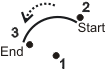
Specifies that the arc feature is built from a geometric construction using the specified base features. (more details...) |
|||||||||||||||||||||||||||||||||||||||
|
Specifies that the arc feature is built from the arc that best fits the specified base features. You can specify three or more edgels or points as base features. It is possible to have a combination of edgels and points. The best fit arc passes as close to as much data as possible while not necessarily touching it. Note that arcs follow the counter-clockwise convention. The angular constraints are ignored for the base features which do not have angle information. 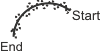
Specifies that the arc feature is built from the arc that best fits the specified base features. (more details...) |
|||||||||||||||||||||||||||||||||||||||
|
Specifies that the arc feature is built from the following MmetControl() parametric controls: M_POSITION_X, M_POSITION_Y, M_ANGLE_START, M_ANGLE_END, and M_RADIUS. |
|||||||||||||||||||||||||||||||||||||||
|
Adds a constructed circle feature. (summarize)Adds a constructed circle feature. (more details...) |
|||||||||||||||||||||||||||||||||||||||
|
Same as M_PARAMETRIC. |
|||||||||||||||||||||||||||||||||||||||
|
Specifies that the circle feature is cloned from the specified base feature. |
|||||||||||||||||||||||||||||||||||||||
|
Specifies that the circle feature is built from a geometric construction using the specified base features. You can specify any two of the following as base features: points, circles, arcs, or local frames. For example, you can specify two point features, or one point and one circle. In all cases, MIL requires two points to construct the circle. If you specify a circle or arc feature, MIL takes its center point. If you specify a local frame feature, MIL takes its origin point. To build the circle, MIL uses the first point as the center of the circle, while the second point is considered to be on the circle's contour. The distance between the two points is the new circle's radius. (summarize)Specifies that the circle feature is built from a geometric construction using the specified base features. (more details...) |
|||||||||||||||||||||||||||||||||||||||
|
Specifies that the circle feature is built from the circle that best fits the specified base features. You can specify three or more edgels or points as base features. It is possible to have a combination of edgels and points. The best fit circle passes as close to as much data as possible while not necessarily touching it. The angular constraints are ignored for the base features which do not have angle information. 
Specifies that the circle feature is built from the circle that best fits the specified base features. (more details...) |
|||||||||||||||||||||||||||||||||||||||
|
Specifies that the circle feature is built from the best inner fit of a circle around the specified base features. You can specify three or more edgels or points as base features. It is possible to have a combination of edgels and points. The inner fit for a circle feature is the largest possible circle that does not contain any edgels or points. The angular constraints are ignored for the base features which do not have angle information. 
Specifies that the circle feature is built from the best inner fit of a circle around the specified base features. (more details...) |
|||||||||||||||||||||||||||||||||||||||
|
Specifies that the circle feature is built from the best outer fit of a circle around the specified base features. You can specify three or more edgels or points as base features. It is possible to have a combination of edgels and points. The outer fit for a circle feature is the smallest possible circle that contains all the edgels or points. The angular constraints are ignored for the base features which do not have angle information. 
Specifies that the circle feature is built from the best outer fit of a circle around the specified base features. (more details...) |
|||||||||||||||||||||||||||||||||||||||
|
Specifies that the circle feature is built from the following MmetControl() parametric controls: M_POSITION_X, M_POSITION_Y, and M_RADIUS. |
|||||||||||||||||||||||||||||||||||||||
|
Adds a constructed edgel feature. (summarize)Adds a constructed edgel feature. (more details...) |
|||||||||||||||||||||||||||||||||||||||
|
Same as M_COPY_FEATURE_EDGELS. |
|||||||||||||||||||||||||||||||||||||||
|
Specifies that the edgel feature is cloned from the specified base feature. |
|||||||||||||||||||||||||||||||||||||||
|
Specifies that the edgel feature is constructed by copying the edgels of the specified base features. You can specify physically measured features or constructed edgel features as base features. For physically measured base features, you can restrict the operation to copy only the active edgels or only the fitted edgels of the base features, using MmetControl() with M_EDGEL_TYPE. For constructed edgel base features, MIL considers the edgels active (not fitted). (summarize)Specifies that the edgel feature is constructed by copying the edgels of the specified base features. (more details...) |
|||||||||||||||||||||||||||||||||||||||
|
Specifies that the edgel feature is constructed from edgels or points established using other MIL modules or third party software. Use MmetPut() to add the edgels/points to the feature. (summarize)Specifies that the edgel feature is constructed from edgels or points established using other MIL modules or third party software. (more details...) |
|||||||||||||||||||||||||||||||||||||||
|
Specifies that the edgel feature is constructed by grouping the edgels of the specified base features. By default, MIL uses all edgels. To change this (for example, to group edgels according to the distance to a point), call MmetControl() with M_GROUP_SELECTION_MODE. (summarize)Specifies that the edgel feature is constructed by grouping the edgels of the specified base features. (more details...) |
|||||||||||||||||||||||||||||||||||||||
|
Adds a constructed line feature. (summarize)Adds a constructed line feature. (more details...) |
|||||||||||||||||||||||||||||||||||||||
|
Same as M_PARAMETRIC. |
|||||||||||||||||||||||||||||||||||||||
|
Specifies that the line feature is built at a specified angle from the specified linear base feature (segment or line), and passing through the specified point base feature. The order in which you specify the base features does not matter. To specify the angle, use MmetControl() with M_ANGLE and set a value between 0° and 360°. The angle is measured counter-clockwise, relative to the linear feature (from start to end). 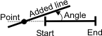
Specifies that the line feature is built at a specified angle from the specified linear base feature (segment or line), and passing through the specified point base feature. (more details...) |
|||||||||||||||||||||||||||||||||||||||
|
Specifies that the line feature is built by dividing an angle formed by the specified base features. You can specify three points or two lines as base features. By default, MIL builds the feature by dividing the angle, formed by the base features, in two equal parts. If three points are specified, the first point is used as the vertex of the angle. 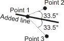
If two lines are specified, the bisector line is built where it divides the angle formed by the first line and the second line in the counter-clockwise direction. 
If specifying two lines as base features, you can use MmetControl() with M_LINE_BISECTOR_TYPE to alter how the new line is built. For example, you can build the bisector line at the middle of the smallest or biggest angle formed by the two line base features. (summarize)Specifies that the line feature is built by dividing an angle formed by the specified base features. (more details...) |
|||||||||||||||||||||||||||||||||||||||
|
Specifies that the line feature is cloned from the specified base feature. |
|||||||||||||||||||||||||||||||||||||||
|
Specifies that the line feature is built from a geometric construction using the specified base features. You can specify any two of the following as base features: points, circles, arcs, or local frames. For example, you can specify two point features, or one point and one circle. In all cases, MIL requires two points to construct the line. If you specify a circle or arc feature, MIL takes its center point. If you specify a local frame feature, MIL takes its origin point. To build the line, MIL ensures that it passes through the two points specified. (summarize)Specifies that the line feature is built from a geometric construction using the specified base features. (more details...) |
|||||||||||||||||||||||||||||||||||||||
|
Specifies that the line feature is built from the resulting best fit of the specified base feature. You can specify a segment as the base feature. (summarize)Specifies that the line feature is built from the resulting best fit of the specified base feature. (more details...) |
|||||||||||||||||||||||||||||||||||||||
|
Specifies that the line feature is built parallel to the specified linear base feature (segment or line), and passing through the specified point base feature. The order in which you specify the base features does not matter. 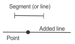
Specifies that the line feature is built parallel to the specified linear base feature (segment or line), and passing through the specified point base feature. (more details...) |
|||||||||||||||||||||||||||||||||||||||
|
Specifies that the line feature is built from the following MmetControl() parametric controls: M_LINE_A, M_LINE_B, and M_LINE_C. |
|||||||||||||||||||||||||||||||||||||||
|
Specifies that the line feature is built perpendicular to the specified linear base feature (segment or line), and passing through the specified point base feature. The order in which you specify the base features does not matter. 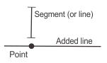
Specifies that the line feature is built perpendicular to the specified linear base feature (segment or line), and passing through the specified point base feature. (more details...) |
|||||||||||||||||||||||||||||||||||||||
|
Specifies that the line feature is built where it divides, in two parts, an angle formed by the specified base features. You can specify three points as base features. The first point is used as the vertex of the angle. Specify the size of the angle between the line and the first pair of points (first and second points) using MmetControl() with M_ANGLE. Express the angle as a percentage of the total angle of all three points. 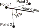
Specifies that the line feature is built where it divides, in two parts, an angle formed by the specified base features. (more details...) |
|||||||||||||||||||||||||||||||||||||||
|
Adds a constructed local frame feature. (summarize)Adds a constructed local frame feature. (more details...) |
|||||||||||||||||||||||||||||||||||||||
|
Same as M_PARAMETRIC. |
|||||||||||||||||||||||||||||||||||||||
|
Specifies that the local frame feature is cloned from the specified base feature. |
|||||||||||||||||||||||||||||||||||||||
|
Specifies that the local frame feature is built from a geometric construction using the specified base features. You can specify any two of the following as base features: points, circles, arcs, or local frames. For example, you can specify two point features, or one point and one circle. In such cases, MIL requires two points to construct the local frame. If you specify a circle or arc feature, MIL takes its center point. If you specify a local frame feature, MIL takes its origin point. To build the local frame, MIL uses the first point as the origin of the local frame and the second point is used to align the X-axis. 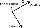
You can also build a local frame by specifying only one feature. In this case, the specified point represents the origin of the local frame. You must use MmetControl() with M_ANGLE to specify the local frame's angle. The angle is applied in the counter-clockwise direction. 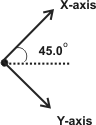
Specifies that the local frame feature is built from a geometric construction using the specified base features. (more details...) |
|||||||||||||||||||||||||||||||||||||||
|
Specifies that the local frame feature is built from the following MmetControl() parametric controls: M_POSITION_X, M_POSITION_Y, and M_ANGLE. Note that the angle is measured counter-clockwise, and is relative to the global frame. (summarize)Specifies that the local frame feature is built from the following MmetControl() parametric controls: M_POSITION_X, M_POSITION_Y, and M_ANGLE. (more details...) |
|||||||||||||||||||||||||||||||||||||||
|
Adds a constructed point feature. (summarize)Adds a constructed point feature. (more details...) |
|||||||||||||||||||||||||||||||||||||||
|
Same as M_PARAMETRIC. |
|||||||||||||||||||||||||||||||||||||||
|
Specifies that the point feature is built at the specified absolute angle, on the contour of the specified base feature. You can specify either an arc or a circle as the base feature. The angle, in degrees, is relative to the start of the contour of the specified feature and is set using MmetControl() with M_ANGLE. The angle is measured counter-clockwise. The start of the contour of a circle is where the circle intersects the positive X-axis at 0°. 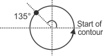
Specifies that the point feature is built at the specified absolute angle, on the contour of the specified base feature. (more details...) |
|||||||||||||||||||||||||||||||||||||||
|
Specifies that the point feature is built at the specified relative angle, on the contour of the specified base feature. You can specify either an arc or a circle as the base feature. Specify the angle as a percentage, relative to the start of the contour using MmetControl() with M_ANGLE. Note that the start of a circle's contour is where the circle intersects with the positive X-axis at 0°. 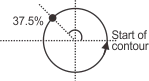
Specifies that the point feature is built at the specified relative angle, on the contour of the specified base feature. (more details...) |
|||||||||||||||||||||||||||||||||||||||
|
Specifies that the point feature is built at the center of the specified base feature(s). You can specify one, or a combination, of the following as base features: arc, circle, edgel, local frame, point, or segment. If multiple features are provided, the point feature is built at the center of gravity of the centers of all the features. 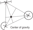
M_CENTER does not necessarily build a point on the feature's edge. Use M_MIDDLE if you want to build a point at the edge's midpoint. (summarize)Specifies that the point feature is built at the center of the specified base feature(s). (more details...) |
|||||||||||||||||||||||||||||||||||||||
|
Specifies that the point feature is cloned from the specified base feature. |
|||||||||||||||||||||||||||||||||||||||
|
Specifies that the point feature is built at the point on the first specified base feature that is, by default, closest to the other (one or more) specified base features. 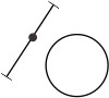
You can specify any features as the base features. The M_CLOSEST operation will fail if the closest point is not unique; for example, a segment and a line that are parallel. You can explicitly specify an angle at which to build the closest point between the features, by calling MmetControl() with M_DISTANCE_MODE. This can be seen as a type of caliper feature. MIL considers the specified distance mode angle at which to measure the closest distance to be relative to the first base feature. MIL applies the angle counter-clockwise. (summarize)Specifies that the point feature is built at the point on the first specified base feature that is, by default, closest to the other (one or more) specified base features. (more details...) |
|||||||||||||||||||||||||||||||||||||||
|
Specifies that the point feature is built, at the position on the base feature, that is the closest to an infinite point. This is a virtual point that MIL establishes, at infinity, along the direction (X-axis) of the local frame. To change the angle along which to establish the infinite point, call MmetControl() with M_ANGLE. MIL measures this angle counter-clockwise, relative to the X-axis of the local frame. 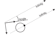
The base features can be any feature except line, which is itself infinite (unbounded). You can, for example, use M_CLOSEST_TO_INFINITE_POINT to establish the boundaries of an edgel feature by fetching the coordinates of the constructed closest infinite points at 0°, 90, 180°, and 270° angles. (summarize)Specifies that the point feature is built, at the position on the base feature, that is the closest to an infinite point. (more details...) |
|||||||||||||||||||||||||||||||||||||||
|
Specifies that the point feature is built at the point of intersection between the extension of the first and second specified base features. Note that the following can be extended: a segment, which is extended into a line, and an arc, which is extended into a circle. You can specify the following as base features:
If there is more than one intersection candidate, specify the index of the intersection at which to build the feature, using MmetControl() with M_OCCURRENCE; the intersection is relative to the first feature that has a direction. The default intersection is the one indexed as 0. 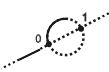
Specifies that the point feature is built at the point of intersection between the extension of the first and second specified base features. (more details...) |
|||||||||||||||||||||||||||||||||||||||
|
Specifies that the point feature is built at the point of intersection between the first and second specified base features. You can specify the following as base features:
If there is more than one intersection candidate, specify the index of the intersection at which to build the feature, using MmetControl() with M_OCCURRENCE; the intersection is relative to the first feature that has a direction. The default intersection is the one indexed as 0. 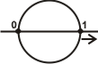
For two circle intersections, specify the intersections relative to the segment that can be created by joining the circles' centers. The first intersection obtained by scanning the first circle counter-clockwise from the segment is indexed as 0; the other is indexed at 1. 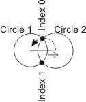
Specifies that the point feature is built at the point of intersection between the first and second specified base features. (more details...) |
|||||||||||||||||||||||||||||||||||||||
|
Specifies that the point feature is built at the point on the first specified base feature that is, by default, farthest from any one point on the other (one or more) specified base features. 
You can specify any feature except line as the first base feature, and any feature as the other base features. The M_MAX_DISTANCE_POINT operation will fail if the farthest point is not unique; for example, a segment and a line that are parallel. Note that the point (on the first base feature) is established regardless of how close it is to the other points (on the other base features). You can explicitly specify an angle at which to build the farthest point between features, by calling MmetControl() with M_DISTANCE_MODE. This can be seen as a type of caliper between the features. MIL considers the specified distance mode angle at which to measure the maximum distance to be relative to the first base feature. MIL applies the angle counter-clockwise. (summarize)Specifies that the point feature is built at the point on the first specified base feature that is, by default, farthest from any one point on the other (one or more) specified base features. (more details...) |
|||||||||||||||||||||||||||||||||||||||
|
Specifies that the point feature is built at the point on the first specified base feature that is the farthest of all the closest points on the second base feature. This point can be considered the maximin (the greatest of all the smallest). 
You can specify any feature except line as the first base feature, and any feature except edgel as the other base features. The M_MAX_OF_MIN_DISTANCE_POINT operation will fail if the point is not unique; for example, a segment and a line that are parallel. Note that the point (on the first base feature) is established regardless of how close it is to the other points (on the other base features). (summarize)Specifies that the point feature is built at the point on the first specified base feature that is the farthest of all the closest points on the second base feature. (more details...) |
|||||||||||||||||||||||||||||||||||||||
|
Specifies that the point feature is built at the midpoint of the contour (edge) of the specified base feature. You can specify a segment, arc, or circle as the base feature. The middle of the contour of a circle is where the circle intersects the negative X-axis at 180°. M_MIDDLE applies to a point, located on the feature's edge, that splits the edge at the halfway mark. Use M_CENTER if you want to build the point feature at the center point of the specified features and not necessarily on the feature's edge. (summarize)Specifies that the point feature is built at the midpoint of the contour (edge) of the specified base feature. (more details...) |
|||||||||||||||||||||||||||||||||||||||
|
Specifies that the point feature is built from the following MmetControl() parametric controls: M_POSITION_X and M_POSITION_Y. |
|||||||||||||||||||||||||||||||||||||||
|
Specifies that the point feature is built at the specified position on the contour of the specified base feature. You can specify a segment, arc, circle, or edgel feature as the base feature. The position is relative to the start of the contour of the specified feature and is set using MmetControl() with M_POSITION. In the example below, M_POSITION has a value of 40 and the provided segment feature has a length of 120. 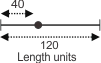
Note that the start of the contour of a circle is where the circle intersects the positive X-axis at 0° and the start of the contour of an edgel feature is the first edgel subfeature of the edgel feature. (summarize)Specifies that the point feature is built at the specified position on the contour of the specified base feature. (more details...) |
|||||||||||||||||||||||||||||||||||||||
|
Specifies that the point feature is built at the end of the contour of the specified base feature. You can specify a segment, arc, circle, or edgel feature as the base feature. The end of the contour of a circle is where the circle intersects the positive X-axis at 360°, which is the same point as its start of contour. The end of the contour of an edgel feature is the last edgel subfeature of the edgel feature. (summarize)Specifies that the point feature is built at the end of the contour of the specified base feature. (more details...) |
|||||||||||||||||||||||||||||||||||||||
|
Specifies that the point feature is built at the specified relative position on the contour of the specified base feature. You can specify a segment, arc, circle, or edgel feature as the base feature. Specify the position as a percentage of the total length of the specified feature's contour, relative to the start of the contour, using MmetControl() with M_POSITION. In the example below, M_POSITION is set to 50%. 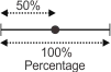
Note that the start of the contour of a circle is where the circle intersects the positive X-axis at 0° and the start of the contour of an edgel feature is the first edgel subfeature of the edgel feature. (summarize)Specifies that the point feature is built at the specified relative position on the contour of the specified base feature. (more details...) |
|||||||||||||||||||||||||||||||||||||||
|
Specifies that the point feature is built at the start position of the contour of the specified base feature. You can specify a segment, arc, circle, or edgel feature as the base feature. The start of the contour of a circle is where the circle intersects the positive X-axis at 0° and the start of the contour of an edgel feature is the first edgel in the edgel feature. (summarize)Specifies that the point feature is built at the start position of the contour of the specified base feature. (more details...) |
|||||||||||||||||||||||||||||||||||||||
|
Adds a constructed segment feature. (summarize)Adds a constructed segment feature. (more details...) |
|||||||||||||||||||||||||||||||||||||||
|
Same as M_PARAMETRIC. |
|||||||||||||||||||||||||||||||||||||||
|
Specifies that the segment feature is cloned from the specified base feature. |
|||||||||||||||||||||||||||||||||||||||
|
Specifies that the segment feature is built from a geometric construction using the specified base features. You can specify any two of the following as base features: points, circles, arcs, or local frames. For example, you can specify two point features, or one point and one circle. In all cases, MIL requires two points to construct the segment. If you specify a circle or arc feature, MIL takes its center point. If you specify a local frame feature, MIL takes its origin point. To build the segment, MIL uses the first point as the start of the segment and the second as the end of the segment. (summarize)Specifies that the segment feature is built from a geometric construction using the specified base features. (more details...) |
|||||||||||||||||||||||||||||||||||||||
|
Specifies that the segment feature is built from the line that best fits the specified base features. You can specify two or more edgels or points as base features. The best fit segment passes as close to as much data as possible while not necessarily touching it. The start of the segment is the extremity closest to the origin of the reference frame. The angular constraints are ignored for the base features which do not have angle information. 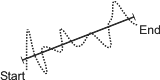
Specifies that the segment feature is built from the line that best fits the specified base features. (more details...) |
|||||||||||||||||||||||||||||||||||||||
|
Specifies that the segment feature is built from the segment that has the best inner fit in the specified base features. You can specify two or more edgels or points as base features. The edgels used to find the inner fit segment are the active edgels on the counter-clockwise side of the best fit segment (from start to end). These active edgels are considered the fitted edgels, since they satisfy the edgel constraints and fit constraints set using MmetControl(). The best fit segment, whose starting point is the extremity closest to the origin of the global frame, separates the inner and outer fit regions. The inner fit segment passes through the two farthest edgels of the inner fit region such that all the edgels of the inner fit region are located on the same side of the inner fit segment. All the active edgels can be projected on the segment, so the segment's extremities are determined by the two farthest active edgels. The angular constraints are ignored for the base features which do not have angle information. 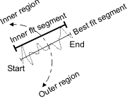
Specifies that the segment feature is built from the segment that has the best inner fit in the specified base features. (more details...) |
|||||||||||||||||||||||||||||||||||||||
|
Specifies that the segment feature is built from the outer fit of the specified base features. You can specify two or more edgels or points as base features. The edgels used to find the outer fit segment are the active edgels on the clockwise side of the best fit segment, relative to its direction. These active edgels are considered the fitted edgels, since they satisfy the edgel constraints and fit constraints set using MmetControl(). The best fit segment, whose starting point is the extremity closest to the origin of the global frame, separates the inner and outer fit regions. The outer fit segment passes through the two farthest edgels of the outer fit region such that all the edgels of the outer fit region are located on the same side of the outer fit segment. All the active edgels can be projected on the segment, so the segment's extremities are determined by the two farthest active edgels. The angular constraints are ignored for the base features which do not have angle information. 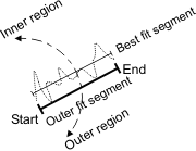
Specifies that the segment feature is built from the outer fit of the specified base features. (more details...) |
|||||||||||||||||||||||||||||||||||||||
|
Specifies that the segment feature is built from the following MmetControl() parametric controls: M_POSITION_START_X, M_POSITION_START_Y, M_POSITION_END_X, and M_POSITION_END_Y. |
|||||||||||||||||||||||||||||||||||||||
To add a measured feature, the FeatureType, Geometry, and BuildOperation parameters can be set to the following values.
|
For adding a measured feature
|
|||||||||||||||||||||||||||||||||||||||
|
|
Description | ||||||||||||||||||||||||||||||||||||||
| Geometry | |||||||||||||||||||||||||||||||||||||||
| BuildOperation | |||||||||||||||||||||||||||||||||||||||
|
Adds a physically measured feature. Measured features are built using data (edgels) extracted from the target image within the metrology region. All fit operations for measured features (M_FIT, M_INNER_FIT, or M_OUTER_FIT) are affected by the minimum and maximum fit settings. You can adjust these using MmetControl() with M_FIT_COVERAGE_MIN, M_FIT_DISTANCE_MAX, M_FIT_ITERATIONS_MAX, and M_FIT_VARIATION_MAX. These settings can alter the precision of the edge that is ultimately fit; however, they might not reliably discard outliers (outlier pixels/points) when they significantly impact the initial fit (the first iteration of the fit). When dealing with a lot of outliers, use a robust best fit (M_FIT), by calling MmetControl() with M_FIT_TYPE set to M_ROBUST_FIT. By default, when specifying a best fit (M_FIT), MIL performs a standard best fit. Fit operations for measured features are also affected by the gradient angle settings, which you can control using M_EDGEL_ANGLE_RANGE and M_EDGEL_RELATIVE_ANGLE. When performing a standard best fit (M_STANDARD_FIT), more importance is typically given to the edgels whose gradient orientation follows the region's orientation. (summarize)Adds a physically measured feature. (more details...) |
|||||||||||||||||||||||||||||||||||||||
|
Adds a physically measured arc feature. In this case, you must use an infinite or a ring-sector metrology region (MmetSetRegion()). (summarize)Adds a physically measured arc feature. (more details...) |
|||||||||||||||||||||||||||||||||||||||
|
Same as M_FIT. |
|||||||||||||||||||||||||||||||||||||||
|
Specifies that the measured arc feature is built using a best fit operation applied to the data (edgels) extracted from the metrology region. The best fit arc passes as close to as much data as possible while not necessarily touching it. 
Specifies that the measured arc feature is built using a best fit operation applied to the data (edgels) extracted from the metrology region. (more details...) |
|||||||||||||||||||||||||||||||||||||||
|
Adds a physically measured circle feature. In this case, you must use an infinite or a ring metrology region (MmetSetRegion()). (summarize)Adds a physically measured circle feature. (more details...) |
|||||||||||||||||||||||||||||||||||||||
|
Same as M_FIT. |
|||||||||||||||||||||||||||||||||||||||
|
Specifies that the measured circle feature is built using a best fit operation applied to the data (edgels) extracted from the metrology region. The best fit circle passes as close to as much data as possible while not necessarily touching it.
Specifies that the measured circle feature is built using a best fit operation applied to the data (edgels) extracted from the metrology region. (more details...) |
|||||||||||||||||||||||||||||||||||||||
|
Specifies that the measured circle feature is built using the best inner fit operation applied to the data (edgels) extracted from the metrology region. The inner fit for a circle feature is the largest possible circle that does not contain any edgels or points.
Specifies that the measured circle feature is built using the best inner fit operation applied to the data (edgels) extracted from the metrology region. (more details...) |
|||||||||||||||||||||||||||||||||||||||
|
Specifies that the measured circle feature is built using the best outer fit operation applied to the data (edgels) extracted from the metrology region. The outer fit for a circle feature is the smallest possible circle that contains all the edgels or points.
Specifies that the measured circle feature is built using the best outer fit operation applied to the data (edgels) extracted from the metrology region. (more details...) |
|||||||||||||||||||||||||||||||||||||||
|
Adds a physically measured edgel feature. In this case, you must use an infinite, rectangle, ring, or ring-sector metrology region (MmetSetRegion()). (summarize)Adds a physically measured edgel feature. (more details...) |
|||||||||||||||||||||||||||||||||||||||
|
Specifies that the measured edgel feature is built by extracting all the edgels in the metrology region. |
|||||||||||||||||||||||||||||||||||||||
|
Adds a physically measured point feature. In this case, you must use an arc, infinite, or segment metrology region (MmetSetRegion()). (summarize)Adds a physically measured point feature. (more details...) |
|||||||||||||||||||||||||||||||||||||||
|
Same as M_FIT. |
|||||||||||||||||||||||||||||||||||||||
|
Specifies that the measured point feature is built using a best fit operation applied to the data (edgels) extracted from the metrology region. |
|||||||||||||||||||||||||||||||||||||||
|
Adds a physically measured segment feature. In this case, you must use an infinite, rectangle, or ring-sector metrology region (MmetSetRegion()). (summarize)Adds a physically measured segment feature. (more details...) |
|||||||||||||||||||||||||||||||||||||||
|
Same as M_FIT. |
|||||||||||||||||||||||||||||||||||||||
|
Specifies that the measured segment feature is built from the line that best fits the data (edgels) extracted from the metrology region. The best fit segment passes as close to as much data as possible while not necessarily touching it. The start of the segment is the extremity closest to the origin of the global frame. 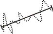
Specifies that the measured segment feature is built from the line that best fits the data (edgels) extracted from the metrology region. (more details...) |
|||||||||||||||||||||||||||||||||||||||
|
Specifies that the measured segment feature is built from the segment that has the best inner fit applied to the data (edgels) extracted from the metrology region. For more information on how an inner fit segment differs from a best fit segment, see M_CONSTRUCTED with M_SEGMENT and M_INNER_FIT. (summarize)Specifies that the measured segment feature is built from the segment that has the best inner fit applied to the data (edgels) extracted from the metrology region. (more details...) |
|||||||||||||||||||||||||||||||||||||||
|
Specifies that the measured segment feature is built from the segment that has the best outer fit applied to the data (edgels) extracted from the metrology region. For more information on how an outer fit segment differs from a best fit segment, see M_CONSTRUCTED with M_SEGMENT and M_OUTER_FIT. (summarize)Specifies that the measured segment feature is built from the segment that has the best outer fit applied to the data (edgels) extracted from the metrology region. (more details...) |
|||||||||||||||||||||||||||||||||||||||
To modify a feature, the FeatureType, Geometry, and BuildOperation parameters can be set to the following values.
|
For modifying a feature
|
|||||||||||||||||||||||||||||||||||||||
|
|
Description | ||||||||||||||||||||||||||||||||||||||
| Geometry | |||||||||||||||||||||||||||||||||||||||
| BuildOperation | |||||||||||||||||||||||||||||||||||||||
|
Modifies the build operation of the specified feature, and/or for a constructed feature, modifies its base features, which is the set of features used to build the constructed feature. To specify the new features from which to construct the specified feature, use FeatureLabelArrayPtr and SubFeatureIndexArrayPtr. (summarize)Modifies the build operation of the specified feature, and/or for a constructed feature, modifies its base features, which is the set of features used to build the constructed feature. (more details...) |
|||||||||||||||||||||||||||||||||||||||
|
Specifies to use the current geometry of the feature. The selected feature's geometry cannot be changed. (summarize)Specifies to use the current geometry of the feature. (more details...) |
|||||||||||||||||||||||||||||||||||||||
|
Specifies to change only the features from which the selected feature is built (its base features) and that the selected feature's build operation should not be changed. |
|||||||||||||||||||||||||||||||||||||||
|
Specifies a new build operation for the selected feature. The new build operation must be appropriate for the feature's geometry. See the For adding a constructed feature or For adding a measured feature table for possible build operations given the feature's geometry. When modifying a constructed feature, you must pass the list of base features from which to construct the specified feature (FeatureLabelArrayPtr and SubFeatureIndexArrayPtr), even if you only need to modify the build operation. (summarize)Specifies a new build operation for the selected feature. (more details...) |
|||||||||||||||||||||||||||||||||||||||
| Header | Include mil.h. |
| Library | Use mil.lib; milmetrol.lib. |
| DLL | Requires mil.dll; milmetrol.dll. |