Calculating and retrieving results
- See also

 Availability
 Previous
- Next

-
The calculation status of features and tolerances (M_STATUS).
-
The feature's measurements (for example, M_LENGTH).
-
The calculated tolerance value in the target image (M_TOLERANCE_VALUE). For example, the actual angle of intersection between two segments.
-
Inquire M_TEMPLATE_REFERENCE_SIZE_X and M_TEMPLATE_REFERENCE_SIZE_Y to allocate an appropriate destination buffer.
-
Pass the metrology context identifier to MmetDraw().
-
Draw the template reference (M_DRAW_TEMPLATE_REFERENCE).
-
Draw the results.
Once you have added features and geometric tolerances to the metrology template (MmetAddFeature() and MmetAddTolerance()), you can perform the Metrology operation (MmetCalculate()). If the features contained in your metrology template are purely constructed features (MmetAddFeature() with M_CONSTRUCTED), you can choose to not pass a target image to MmetCalculate() and perform calculations on the constructed features.
To calculate correct results, it is important to note the calculation units (world or pixel), and the location of the reference frame (in the target image), before calling MmetCalculate(). If a camera calibration context has been associated with the target image, all tolerance and feature values (as well as metrology regions and positions) must have been set in the real-world. For more information, see the Camera calibration - overview section of Chapter 26: Calibrating your camera setup. If the position of a reference frame within the metrology template does not correspond to the same position in the target image, you must reposition the reference frame. For more information, see the Set position subsection of the Features section earlier in this chapter.
By default, there is no limit set for the calculation time. However, the calculation can occasionally be unexpectedly long. To handle this, you can use MmetControl() with M_TIMEOUT to set a maximum calculation time. To check whether this limit has been reached, you can use MmetGetResult() with M_TIMEOUT_END.
Once you have performed the Metrology operation, you can retrieve the results from your metrology result buffer, using MmetGetResult() with either the label of the feature or the label of the geometric tolerance.
Retrieving the results
Metrology offers several types of results that provide considerable feature and tolerance information. Typically, you retrieve results from your result buffer for one feature or one tolerance at a time. Examples of results that you can retrieve include:
To verify the availability of a metrology result (if it has been calculated), use MmetGetResult() and combine M_AVAILABLE to the specified result type.
Status of features and geometric tolerances
Two of the most critical results that you will typically retrieve are the calculation status of your features and geometric tolerances. To do so, use MmetGetResult() with M_STATUS.
The status of the feature returns M_PASS if the feature was successfully validated and M_FAIL if it was not. There are many circumstances that can cause the feature to be invalid. For example, a feature is invalid if it does not exist in the specified metrology region of the target image; in this case, you might need to move the reference frame (MmetSetPosition()). A feature can also be invalid if the information provided is insufficient; this will occur, for example, if you try to construct a point of intersection between two physically measured segments that never actually cross one another.
If a feature is guaranteed to fail, for example, due to its dependency on another process, you can disable the feature for calculation using MmetControl() with M_ACTIVE set to M_DISABLE. This might save you processing time. If you disable a feature, it is not calculated and the status of the feature (M_STATUS) will return M_FAIL. This is also the case for the status of all the derived features and tolerances, if any. You can re-enable the feature for calculation using MmetControl() with M_ACTIVE set to M_ENABLE. This is the default value.
The status of the geometric tolerance returns M_PASS or M_WARNING if the tolerance was successfully validated and M_FAIL if it was not. Since the Metrology module provides highly sensitive measurement calculations, tolerances will fail unless they are strictly adhered.
You can also use M_STATUS to retrieve a global status, which refers to the status of multiple statuses. For example, by calling MmetGetResult() with M_GENERAL and M_STATUS, you will get the global status of all the features and tolerances. This global status returns M_PASS if the status of each feature and tolerance is M_PASS. If any individual status is M_FAIL, you will get M_FAIL. If there is no individual status with M_FAIL, but one or more with M_WARNING, you will get M_WARNING.
Output frame
By default, feature results are returned according to the global frame, even if the feature is defined relative to a local frame. To change the frame used to return feature results (output frame), use MmetControl() with M_OUTPUT_FRAME. You can set the output frame to the feature's reference frame (M_REFERENCE_FRAME), any local frame (valid label of a local frame feature), the target image (M_IMAGE_FRAME), or the global frame (M_GLOBAL_FRAME).
For example, the following image shows how the X- Y-position of a point feature can be (6,5), (3,3), or (1,1) depending on whether the output frame is set to the global frame, the local frame, or the image frame.

For more information on global and local frames, see the Reference frame subsection of the Features section earlier in this chapter.
Annotating the results
MmetDraw() provides several operations for drawing in any specified image buffer. For example, you can draw the extracted edgels (M_DRAW_ALL_EDGELS), the active edgels (M_DRAW_ACTIVE_EDGELS), a successfully validated feature (M_DRAW_FEATURE), the features used to define a geometric tolerance (M_DRAW_TOLERANCE_FEATURES), the area used to define an area-based geometric tolerance (M_AREA_...), and the icon that represents the geometric tolerance (M_DRAW_TOLERANCE). To view the geometric tolerance icons, see the Geometric tolerances section earlier in this chapter.
You can also choose to draw in the display's overlay buffer. By drawing into the display's overlay buffer, you can annotate an image non-destructively (see the Annotating the displayed image non-destructively section of Chapter 23: Displaying an image).
If you are using a calibrated target image, the camera calibration is taken into account when drawing your results; that is, drawings might be distorted, according to the camera calibration. For example, a straight line in the world might be drawn as a curve in the image.
MmetDraw() also allows you to draw features measured and validated in a zoomed region (of the target image from which results were obtained) by specifying the appropriate values for MgraControl() with M_DRAW_OFFSET_X, M_DRAW_OFFSET_Y, M_DRAW_ZOOM_X, and M_DRAW_ZOOM_Y control types. The relative origin values specify, in pixels, the coordinates of the center of the top-left pixel of the region in the target image, while the scale values specify the X- and Y-scaling factors used to fill the destination image buffer.
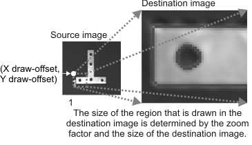
When zooming, MmetDraw() will draw in the destination image buffer even if the buffer is not large enough to contain all of the zoomed image from the specified starting point. If necessary, the image will be clipped.
When drawing all features or tolerances of a context, it can be difficult to visually differentiate between them if there are many. For example, some metrology contexts can have hundreds of features and tolerances, some of which you do not need to see, such as intermediate features that are only needed to build your final set of required features. To specify that a feature or tolerance in the context should not be drawn, use MmetControl() with M_DRAWABLE set to M_DISABLE. When features or tolerances are not drawn, you cannot affect them in an interactive display.
Template reference
A template reference is an image or result buffer that you can use as an example of a target image. Since it provides a visual sample, a template reference can help you build or modify a metrology template.

To set a template reference, use MmetControl() with M_TEMPLATE_REFERENCE_ID. In this case, you can draw the results of features and tolerances extracted from that template reference. To do so, you will need to:
Note that the template reference does not in any way affect metrology calculations.