Geometric tolerances
- See also

 Availability
 Previous
- Next

-
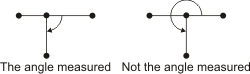
Two segment features.
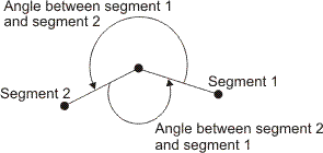
To validate the angularity between two segment features, MIL internally connects each segment at their start point and considers the angle between them to be, counter-clockwise, from the first segment to the second segment. This angle is valid if it falls within the angular range set by the minimum and maximum tolerance limits. To designate the valid angular range, the minimum and maximum tolerance limits are angles applied counter-clockwise around the start point of the first segment. Note that MIL does not physically rearrange the specified segments, it only orients them internally to measure the required angles. The following animation illustrates angularity.

Each segment's start point, as well as the order you list the segments in the FeatureLabelArrayPtr parameter, can affect your results. For example, the angle between segment 1 and segment 2 is different than the angle between segment 2 and segment 1.
-
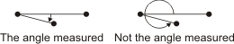
Two line features.
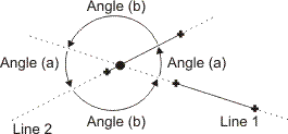
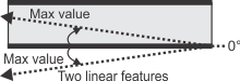
To validate the angularity between two line features, MIL considers the angle between them to be, counter-clockwise, from the first line to the second line. This angle is valid if it falls within the angular range set by the minimum and maximum tolerance limits. To designate the valid angular range, the minimum and maximum tolerance limits are angles applied counter-clockwise, from the first line to the second line, around the intersection point of the two lines.

The order you list the lines in the FeatureLabelArrayPtr parameter can affect your results. For example, the angle between line 1 and line 2 is different than the angle between line 2 and line 1.
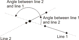
Since lines are infinite, there are actually two ways to measure the angle between line 1 and line 2 (indicated as angle (a) in the following diagram) and between line 2 and line 1 (indicated as angle (b) in the following diagram). Note that this is inconsequential since each pair of angles is equivalent.
-
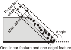
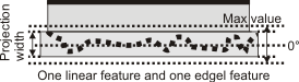
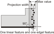
A linear feature (segment or line) and an edgel feature.
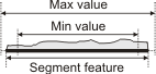
For one linear feature (segment or line) and one edgel feature, M_ANGULARITY validates the width of the projection of the edgel feature, along the nominal angle specified using MmetControl() with M_ANGLE. The angle is in the counter-clockwise direction relative to the linear feature. The minimum and maximum tolerance parameters set the valid projection width. Typically, you should set the minimum width value to 0. The width of the projection is in pixel or world units. The second feature specified in the FeatureLabelArrayPtr parameter must be edgel.
-
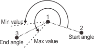
Three point features.
To validate the angularity between three point features, MIL considers the first point as the center of the angularity tolerance, the second point as the StartAngle (in the counter-clockwise direction relative to the first point), and the third point as the EndAngle (in the counter-clockwise direction relative to the first point). M_ANGULARITY validates the angle that results from EndAngle - StartAngle.
-
A tolerance for the typical area or perimeter of a feature's surface (M_AREA_SIMPLE or M_PERIMETER_SIMPLE).
-
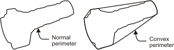
A tolerance, based on the convex hull, for the area or perimeter of a feature's surface (M_AREA_CONVEX_HULL or M_PERIMETER_CONVEX_HULL). Abstractly, you can consider the convex hull like placing a rubber band around the feature, and then calculating the area or perimeter.
-
A tolerance for the area between two curves of edgels (M_AREA_BETWEEN_CURVES), and a tolerance for the maximum or minimum area under a curve of edgels or points (M_AREA_UNDER_CURVE_MAX or M_AREA_UNDER_CURVE_MIN) and a line.
-
Two linear features (segments and lines).
-
A linear feature (segment or line) and an edgel feature.
-
Two linear features (segments and lines).
-
A linear feature (segment or line) and an edgel feature.
After adding features to the metrology template, you will typically add geometric tolerances, using MmetAddTolerance(). A geometric tolerance defines the acceptable deviation from the definition of a feature, or the acceptable geometric relationship between multiple features.
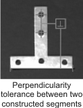
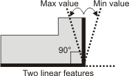
When adding a geometric tolerance, you must set its minimum and maximum limit values. When defining the tolerance of one feature, these limits represent the acceptable deviation from the definition of the feature. For example, a segment's length tolerance can be between 90 and 100 pixels. For multiple features, these limits represent the valid range of acceptable values between the features. For example, the perpendicular tolerance between two segments can be +/- 0.05° (that is, 89.95° to 90.05°). To change the minimum and maximum limit values, use MmetControl() with M_VALUE_MIN and M_VALUE_MAX. You can also use MmetControl() with M_VALUE_WARNING_MIN and M_VALUE_WARNING_MAX to set warning values to alert you when the tolerance is close to its minimum and maximum limits.
When you call MmetCalculate(), the tolerance is calculated (for example, 95 pixels) and a status is assigned (for example, M_PASS). To retrieve the tolerance value and status, use MmetGetResult() with M_TOLERANCE_VALUE and M_STATUS.
The status of the geometric tolerance returns M_PASS or M_WARNING if the tolerance meets the specified requirements, and M_FAIL if it does not. M_FAIL is returned when a tolerance value falls outside the range defined by the minimum and maximum tolerance values and/or the minimum and maximum warning values. M_WARNING is returned when a tolerance value is less than or equal to the minimum tolerance value, but greater than the minimum warning value. A warning also occurs when a tolerance value is greater or equal to the maximum tolerance value, and less than the maximum warning value. M_PASS is returned when the value is between the minimum and maximum tolerance values. By default, the minimum and maximum tolerance and warning values are 0. The following is an example of (non-zero) minimum and maximum tolerance and warning values:
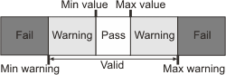
Note that a warning will never be returned if the warning range is within the pass range.
If a calibration context is associated with the target image, set values in real-world units. Otherwise use pixel units (for example, tolerance values and warning values, and positional values). For more information, see the Camera calibration - overview section of Chapter 26: Calibrating your camera setup.
Adding a geometric tolerance
With MmetAddTolerance(), you can add one of the following geometric tolerances:
|
|
|
|
|
|
|
|
|
|
|
|
|
|
|
|
|
|
|
|
|
|
|
|
This table illustrates the tolerance's icon, which you can draw by calling MmetDraw() with M_DRAW_TOLERANCE. For more information about drawing, see the Annotating the results subsection of the Calculating and retrieving results section later in this chapter.
Angularity
An angularity tolerance (M_ANGULARITY) validates that the angle between two features falls within the specified angular range (for example, that two lines intersect at an angle between 25° and 35°). An angularity tolerance can be applied between the following features.
Note that an angularity tolerance between a segment and a line produces too many ambiguities and therefore cannot be calculated.
Area and perimeter
You can add the following tolerances, based on area or perimeter:
Concentricity
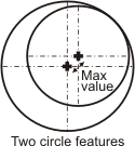
A concentricity tolerance (M_CONCENTRICITY) validates that two features have a common center. A concentricity tolerance can be applied to circle and arc features. The minimum and maximum tolerance parameters set the valid minimum and maximum distance allowed between the center of each feature. Typically, you should set the minimum distance value to 0.
Distance
A distance tolerance (M_DISTANCE_MAX and M_DISTANCE_MIN) validates that the distance between two features meets either the specified maximum or minimum distance values. You can use a maximum distance tolerance with any two features except lines (as lines are infinitely long); you can use a minimum distance tolerance with any two features. The maximum and minimum tolerance parameters set the valid maximum and minimum distances between features for either the maximum or minimum distance tolerance.
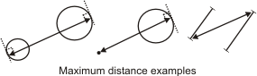
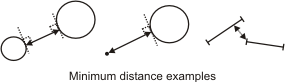
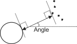
By default, to validate the tolerance, MIL uses the distance at which the features are either the farthest (for M_DISTANCE_MAX) or the closest (for M_DISTANCE_MIN). You can however explicitly specify an angle at which to apply the distance tolerance between two features, by calling MmetControl() with M_DISTANCE_MODE. This can be seen as a type of caliper tolerance between the features. The following example shows how MIL applies the minimum distance tolerance between a circle and an edgel feature at a specific angle.
Length
A length tolerance (M_LENGTH) validates that the linear dimension of one feature meets the specified value. A length tolerance can be applied to one of the following features: segment, edgel, circle, or arc. For circle and arc, length refers to the circumference. The minimum and maximum tolerance parameters set the valid minimum and maximum lengths of the feature.
Parallelism
A parallelism tolerance (M_PARALLELISM) validates the degree to which two features are parallel. A parallelism tolerance can be applied between the following:
For any combination of 2 linear features, M_PARALLELISM validates that the angle of the two features, relative to the global reference frame, is the same. The minimum and maximum tolerance parameters set the valid angular range, from the nominal angle (0°). In this case, you should only set the maximum tolerance parameter; MIL uses it as both the maximum and minimum value. The order of the features specified in the FeatureLabelArrayPtr parameter, as well as the start/end of the segments, is inconsequential.
For parallelism tolerances between two linear features, angles are remapped to 0°; that is, the angle that is measured, and the angular range that you must provide, is the angle that is closest to 0°.
For a linear feature and an edgel feature, M_PARALLELISM validates the width of the projection of the edgel feature on a theoretical line perpendicular to the segment or line feature. The minimum and maximum tolerance values set the valid projection width. The smaller the width, the more the edgel feature is parallel to the given segment or line feature. Typically, the minimum width value is 0. The width of the projection is in pixel or world units. The second feature specified in the FeatureLabelArrayPtr parameter must be edgel.
Perpendicularity
A perpendicularity tolerance (M_PERPENDICULARITY) validates the degree to which two features are perpendicular. A perpendicularity tolerance can be applied between the following features:
For any combination of 2 linear features, M_PERPENDICULARITY validates that the angle between the two features is 90°. The minimum and maximum tolerance parameters set the valid angular range, from the nominal angle (90°). The order of the features specified in the FeatureLabelArrayPtr parameter, as well as the start/end of the segments, is inconsequential.
For perpendicularity tolerances between two linear features, angles are remapped to 90°; that is, the angle measured and the angular range you provide is the angle closest to 90°.
For a linear feature and an edgel feature, M_PERPENDICULARITY validates the width of the projection of the edgel feature on a theoretical line parallel to the segment or line feature. The minimum and maximum tolerance values set the valid projection width. The smaller the width, the more the edgel feature is perpendicular to the given segment or line feature. Typically, the minimum width value is 0. The width of the projection is in pixel or world units. The second feature specified in the FeatureLabelArrayPtr parameter must be edgel.
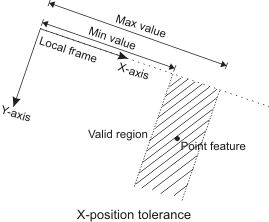
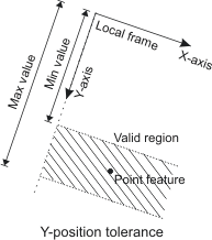
Position
A position tolerance (M_POSITION_X and M_POSITION_Y) validates that a feature must be located at the specified position, along the X- or Y-direction of the specified reference frame. A position tolerance can be applied to a local frame feature, and one of the following features: local frame, point, circle. The minimum and maximum tolerance parameters set the valid minimum and maximum positions for either the X- or Y-position tolerance. If you only specify one feature, MIL validates the geometric relationship between that feature and its reference frame (every feature is associated to a reference frame).
Radius
A radius tolerance (M_RADIUS) validates that the linear length between the feature's center and perimeter falls within the specified values. A radius tolerance can be applied to one of the following features: arc or circle. The minimum and maximum tolerance parameters set the valid minimum and maximum radius of the feature.
Roundness
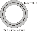
A roundness tolerance (M_ROUNDNESS) validates that a feature is round. This is done by calculating the distance between the inner and outer circular curves formed by the given feature, such as the circle feature shown below. Note that the inner and outer circular curves are concentric.
A roundness tolerance can be applied to circle, arc, and edgel features. The minimum and maximum tolerance parameters set the valid minimum and maximum width between the two concentric curves (for non circle features, this can be seen as portions of a circle). Typically, you should set the minimum width value to 0.
Straightness
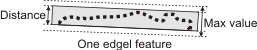
A straightness tolerance (M_STRAIGHTNESS) validates that a feature is straight. This is done by calculating the distance between the two parallel lines that are formed by the inner and outer boundaries of the feature. The angle of the two parallel lines is chosen such that the distance between them is the smallest.
A straightness tolerance can be applied to segment and edgel features. The minimum and maximum tolerance parameters set the valid minimum and maximum width between the two parallel lines. Typically, you should set the minimum width value to 0.
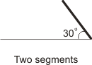
Using multiple geometric tolerances
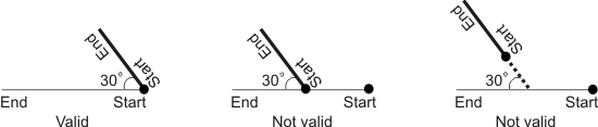
To accurately represent a relationship between features, the features might have to be validated by multiple geometric tolerances. For example, to verify the following result, you might set a 30° angularity tolerance between two segments.
However, using only the angularity tolerance, each of the following results has a valid tolerance status.
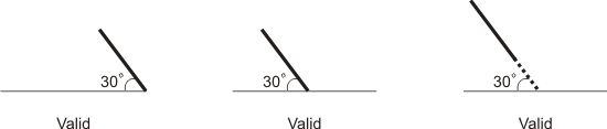
In this case, you need an additional tolerance to check the location of the segments. To do so, you would add two constructed point features at the start of each segment, using MmetAddFeature() with M_POINT and M_POSITION_START. You would then add a distance tolerance for these two points, ensuring they are at the same location. To satisfy the required feature relationship, both the angularity status of the segments and the distance status of the points must be valid.