Calibrating using a fiducial grid
- See also

 Availability
 Previous
- Next

-
Enable the use of a Data Matrix code as a fiducial, using M_GRID_FIDUCIAL set to M_DATAMATRIX.
-
Enable the use of partial grids, using M_GRID_PARTIAL set to M_ENABLE, since the Data Matrix code covers part of the grid.
-
Ensure there is no hint pixel or hint angle by setting M_GRID_HINT_PIXEL_X, M_GRID_HINT_PIXEL_Y, and M_GRID_HINT_ANGLE_X to M_NONE. This is the default setting, so this is typically unnecessary.
-
Set the row number and column number parameters to M_UNKNOWN.
-
Set the row spacing and column spacing parameters to M_FROM_FIDUCIAL.
Note that if you calibrate with a fiducial grid and set these parameters to specific values, the values that you specify will override the values encoded in the Data Matrix code.
-
Set the grid type to M_CHESSBOARD_GRID.
-
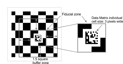
The Data Matrix code in the image of your fiducial grid must have a sufficient buffer zone around it. The squares that the fiducial is placed upon are known as the fiducial zone. To recognize the fiducial in the grid, the camera must see at least 1.5 squares between the fiducial zone and the edge of the grid on all sides, as illustrated in the image below. If the fiducial is too close to the edge of the image, McalGrid() might not recognize the fiducial, which will cause the camera calibration to fail.
-
Calibrating your camera setup using a fiducial grid works with all camera calibration modes, but it is not recommended for M_LINEAR_INTERPOLATION mode, which is the default calibration mode. This is because the fiducial rests on top of one or more calibration points, effectively removing the point(s) from the grid. The effect of the missing calibration points in M_LINEAR_INTERPOLATION mode is local inaccuracy; the camera calibration around the area in the image that has the missing calibration points will be less accurate. Note that the effect of the missing calibration points in the other camera calibration modes is still inaccuracy, but the inaccuracy is evenly distributed across the entire image, making it nearly irrelevant.
-
Calibrating a low-resolution camera using a fiducial grid is not recommended. Low resolution images might have Data Matrix codes that are difficult to decode. Also, low-resolution images will mean bigger calibration squares and therefore have fewer calibration points, which leads to a less accurate calibration. At minimum, the image resolution and image size must allow the individual cells in the Data Matrix code to be at least 3x3 pixels.
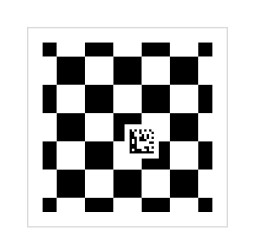
Another way to calibrate your camera setup and have MIL automatically establish the calibration points is to use a fiducial grid, as in the image below. A fiducial grid is a chessboard grid that contains a fiducial. The fiducial used in a fiducial grid is a Data Matrix code that encodes information about the grid itself. This encoded grid information includes the grid spacing, the units in which the spacing is measured, the position of the grid's reference calibration point, and the grid's orientation.
Calibrating with a fiducial grid is especially useful when calibrating multiple cameras or multiple camera positions in a single coordinate system. It can be difficult to find a common reference calibration point shared by all the images of the same grid taken at different angles and positions. By using a fiducial grid that encodes a specific reference calibration point, any image of the grid, regardless of its orientation or position, will have the same known reference calibration point.
The following image is a 6x6 fiducial grid.
MIL is distributed with a fiducial grid that you can print and use: FiducialCalibrationGrid_Letter.pdf, located in the Matrox Imaging\Images directory. However, you can also generate your own fiducial grid by running the CalGenChessGrid example, accessible from the Matrox Example Launcher. For information on how to modify the example to generate a fiducial grid specific to your setup, see the Generating a grid for calibration section later in this chapter.
To calibrate your camera setup using a fiducial grid, you need to set a few control types, grab an image of the fiducial grid, and call McalGrid().
Requirements when calibrating your camera setup using a fiducial grid
The Data Matrix code in the grid encodes real-world information about the grid.
Calibrating your camera using a valid fiducial grid requires you to set the following control types using McalControl():
Once these control types are set, you can grab an image of the grid and call McalGrid() with the following parameter values:
The image of the grid must meet the following requirements:
Defining the absolute coordinate system with a fiducial grid
Calibrating a camera setup, regardless of the calibration mode or type of grid, defines the absolute coordinate system in the world. For a fiducial grid, like the chessboard grid and circle grid, the absolute coordinate system's origin and orientation are determined by the grid's features, such as the grid's reference calibration point and orientation, and the parameter values of McalGrid().
Note that while McalGrid() typically defines the absolute coordinate system directly, it can be used to define the relative coordinate system directly and the absolute coordinate system indirectly using McalControl() with M_CALIBRATION_PLANE. For more information, see the Defining the relative coordinate system directly subsection of the Calibrating using calibration points from a grid section earlier in this chapter.
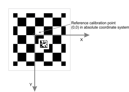
Determining the grid's reference calibration point
The fiducial grid's reference calibration point is an important component of defining the absolute coordinate system, but it cannot be directly observed from the grid itself; the position of the grid's reference calibration point is encoded in the Data Matrix code. The grid's reference calibration point is typically the calibration point to the top-left of the fiducial in the grid. This is the default position when creating your fiducial grid using the CalGenChessGrid example.
The reference calibration point can be anywhere on the grid and its position can only be determined after the Data Matrix code is read. With the default fiducial grid output from the CalGenChessGrid example, there are marks on the outside of the grid that signify where the reference point is. These marks are not, strictly speaking, part of the grid itself.
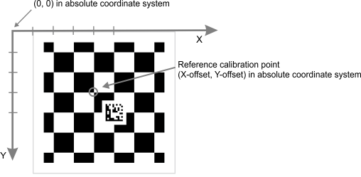
In practice, McalGrid() finds the Data Matrix code, reads the code, and then sets the grid's reference calibration point accordingly. The following illustration shows a fiducial grid with the default reference calibration point and the absolute coordinate system that results from the grid.
For more information about specifying the position of the grid's reference calibration point and the fiducials, see the Specifying the grid's fiducials subsection of the Generating a grid for calibration section later in this chapter.
Orientation of the fiducial grid in the image
The position (and offset, if any) of the fiducial in the grid determines where the grid's reference calibration point is, but the reference calibration point does not determine the orientation of the fiducial grid. The orientation of the fiducial grid is determined by the orientation of the fiducial.
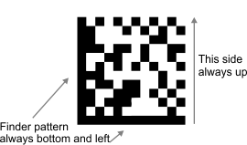
A Data Matrix code has a known orientation. It has a solid black L-shaped finder pattern on its bottom and left side, and a checkered pattern on its top and right side.
Since the orientation of the Data Matrix code is always known, the direction of the X- and Y-axes are always known, even if the fiducial grid is rotated. In the following image, the fiducial grid is rotated 45° and is slightly askew, yet the grid's reference calibration point and the grid orientation are automatically known because of the features of the Data Matrix code.

Note that it is not advisable to use a grid that occupies so little of the entire camera's field of view, as in the image above. Those areas of the image (the camera's field of view) that do not have calibration points will not be accurately calibrated.
Specifying the position and orientation of the absolute coordinate system when calling McalGrid()
A fiducial grid has a fixed reference calibration point and orientation, but these are only the starting points of determining the origin and orientation of the absolute coordinate system. Like with chessboard grids and circle grids, you can apply an offset and/or invert the orientation of the Y-axis of the absolute coordinate system when calling McalGrid().
Typically, when you call McalGrid(), you specify 0 for the X- and Y-offset parameters. This means that typically, the grid's reference calibration point is the origin of the absolute coordinate system. You can, however, specify any value for the offsets; the offsets are specified in real-world units.
When you specify an X- or Y-offset, you move the origin of the absolute coordinate system away from the grid's reference calibration point. The reference calibration point will have the coordinates specified by the X- and Y-offsets. For example, when calling McalGrid(), if you set the X- and Y-offsets to 3 and 4, respectively, the grid's reference calibration point would have the coordinates (3, 4) in the absolute coordinate system.
Even though the orientation of a fiducial grid is fixed, you are still able to invert the direction of the Y-axis in the absolute coordinate system, using McalGrid() with M_Y_AXIS_COUNTER_CLOCKWISE. In this case, the Y-axis of the absolute coordinate system will be 90° counter clockwise from the X-axis, instead of the default 90° clockwise from the X-axis. Note that for 3D camera calibration setups, the Z-axis also inverts when you invert the Y-axis. Typically, the Z-axis is facing down into the working area, but once the Y- axis is inverted, the Z-axis will point up, towards the camera.
Inquiring camera calibration information after successful calibration
After a successful calibration with a fiducial grid, you can inquire the grid spacings (McalInquire() with M_ROW_SPACING or M_COLUMN_SPACING). You can inquire the unit used to describe the spacings (which is also the unit used for all positions returned by the module) using McalInquire() with M_GRID_UNITS or M_GRID_UNIT_SHORT_NAME, to get a constant or a string, respectively.
| M_GRID_UNITS | |
|
units |
|
|
Metric Units |
|
|
um |
|
|
mm |
|
|
cm |
|
|
m |
|
|
km |
|
|
Imperial Units |
|
|
mils |
|
|
in |
|
|
ft |
|
|
miles |
|
Note that MIL does not enforce unit consistency when mixing results from different calibrations, nor does it perform any unit conversion.
Calibrating multiple cameras or camera positions using a fiducial grid
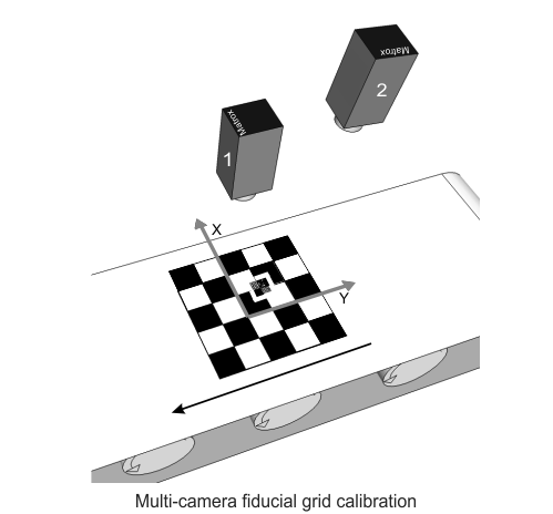
One of the best uses for a fiducial grid is for calibrating multiple cameras or camera positions. If you have more than one camera whose images need to share the same absolute coordinate system, using a fiducial grid is recommended. Consider the following working area and camera setup, where two cameras will grab images of a conveyor.
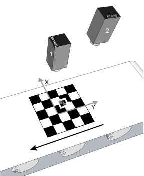
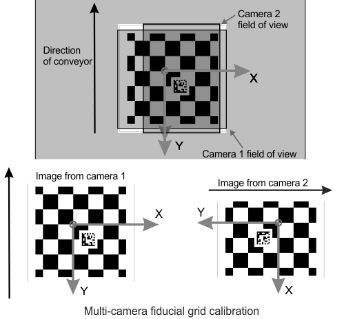
Looking from above, the fiducial grid covers most of the working area. Camera 1 can see the entire grid, but camera 2, which is rotated 90°, cannot see the entire grid, as in the image below. You grab an image of the fiducial grid with camera 1 and use it to calibrate camera 1. The orientation and position of the absolute coordinate system is established using the reference calibration point and the orientation of the fiducial grid. When you grab an image of the same unmoved fiducial grid with camera 2, the image appears to be rotated. Calibrating camera 2 with this image will produce the same absolute coordinate system, despite appearing differently.
The animation below illustrates camera calibration using a fiducial grid.
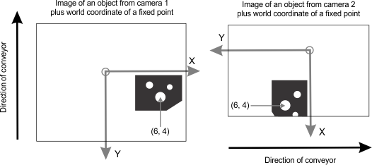
Once these cameras are calibrated and have the same absolute coordinate system, an unmoved object that both cameras can see will have the same coordinates for the same point on the object, despite appearing in very different positions in the image, as illustrated below.
The example above is for two cameras, but could easily apply to one camera that is moved to different positions during camera calibration, as is the case when calibrating your camera in M_3D_ROBOTICS camera calibration mode.
Note that it is essential that each camera be able to see a fiducial in the grid. If there is no way to position your cameras and/or fiducial grid so that at least one complete fiducial is in the field of view of every camera, you must create a new fiducial grid that has either more fiducials or better placed fiducials.
Multi-fiducial grids
Sometimes your working area is too large for your cameras' field of view and at least one camera cannot see the fiducial. In this case, you must create a new fiducial grid that has more than one fiducial.
For example, in the image below, the overlap of the two cameras' field of view is too narrow for the fiducial zone to satisfy the requirement of being 1.5 chessboard squares away from the edge of the image. This means that there is no spot for the fiducial to satisfy this constraint for both cameras. A second fiducial is added so that both cameras can be calibrated using a fiducial grid.
Each fiducial in the grid encodes where the grid's reference calibration point is with regards to itself. In the image below, fiducial 1 encodes an X-offset of +2 and a Y-offset of -2. This means that the grid's reference calibration point is two calibration points left and two calibration points down from fiducial 1. Fiducial 2 specifies the exact same reference calibration point (there can be only one), but encodes an X-offset of -3 and a Y-offset of +1. This means that the grid's reference calibration point is three calibration points right and one calibration point up from fiducial 2.
If you have multiple fiducials and one of your cameras is able to see two or more of them, McalGrid() will only decode one of them. As long as your fiducial grid is valid, decoding any one will have the same result. The position of each fiducial perfectly matches its encoded offsets so that every fiducial on the grid points to the same calibration point as the grid's reference calibration point. If your fiducial grid is invalid, for whatever reason, no error will occur, but the results will be uncertain.

Note that the grid's reference calibration point does not have to be in the image. In the above image, the grid's reference calibration point is not in camera 2's field of view.