Advanced edge extraction
- See also

 Availability
 Previous
- Next

-
The edge to split. This is identified by the edge's label value.
-
The point at which to split the edge. This is identified by the edgel's index value.
-
The portion of the edge to select. This is identified by all edgels in the specified edge with index values that are greater than, less than, greater than or equal to, or less than or equal to, the point at which the edge was split.
-
The X-coordinate(s) of the edgel(s).
-
The Y-coordinate(s) of the edgel(s).
In addition to the fundamental edge extraction settings, Edge Finder provides advanced settings that allow you to write customized applications. Edges can be approximated, masked, cropped, and extracted using advanced thresholding settings. You can provide your own derivative images, and you can put data from user-supplied arrays into an Edge Finder result buffer. You can also get edgels, from an Edge Finder result buffer, which are the closest neighbors to a list of user-specified edgel coordinates.
Approximating the edges
If you are interested in a basic, geometric representation of the edge map, you can approximate your edges by specifying a polygonal segmentation. To do so, set MedgeControl() with M_CHAIN_APPROXIMATION to M_LINE. The default setting is M_DISABLE.
When M_CHAIN_APPROXIMATION is set to M_LINE, each edge is piecewise approximated using a connected series of straight line segments, commonly called polylines. The polylines are defined by the set of automatically calculated vertex coordinates, which determine the location of the line segment ending points. Use MedgeGetResult() to retrieve the X- (M_VERTICES_X) and Y- (M_VERTICES_Y) coordinates of the vertices. This information can be retrieved for either a group of edges or a particular edge. You can also get the index of each vertices' corresponding edge or edgel, using MedgeGetResult() with M_VERTICES_CHAIN_INDEX and M_VERTICES_INDEX, respectively.
The resolution of the edge approximation can be adjusted using MedgeControl() with M_APPROXIMATION_TOLERANCE. The range of this control varies from 0 to 100. When set to 0, a very fine approximation of the edges is performed. When set to 100, a coarse approximation of the edges is performed. The default value is 50. The following animation shows the effects of chain approximation.
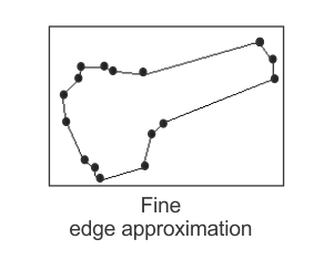
When M_CHAIN_APPROXIMATION is set to M_LINE, both the edge map and the edge approximation is calculated. When M_CHAIN_APPROXIMATION is disabled, only the edge map is calculated.
Masking the edges
The MedgeMask() function allows you to apply a mask to the source image of the Edge Finder operation. A mask is a binary image used to define irrelevant, inconsistent, or featureless areas in the source image. As a result, when a mask is set, subsequent calls to MedgeCalculate() will only extract edges in the source image's unmasked regions.
To set a mask, you must specify an image buffer (also known as a mask buffer) that identifies the masked pixels, using MedgeMask(). A masked pixel in the source image corresponds to a non-zero value in the mask buffer. Mask buffers are useful for creating non-rectangular areas to be processed. For rectangular areas, it is more effective to set a mask with child buffers. For more information, see the Using child buffers, ROIs, or a copy to manipulate specific data areas section of Chapter 21: Data buffers.
If necessary, you can remove the mask by setting the mask buffer identifier to M_NULL.
You can also mask edges during post-calculation. To do so, you must apply the mask after the initial call to MedgeCalculate(). In this case, masked edges are excluded from the result buffer and subsequent calculations. Note that partially masked edges are cropped.
Cropping the edges
Selecting an edge or a group of edges for calculation and result retrieval is typically sufficient for the majority of cases. However, in some advanced applications, you might only be interested in one part of a single edge. In this case, you can use MedgeSelect() with M_CROP_CHAIN.
Cropping an edge essentially means splitting one edge into two, thereby allowing you to choose only one of the edges to be included, excluded, or deleted from the Edge Finder result buffer. The selected portion receives a new label value, while the other portion keeps the original label value.
You can make as many cropping operations as necessary to arrive at the required set of results. Note that all calculated edge features are updated after each cropping operation.
To split an edge into two edges, you must specify the following:
The following code shows you how to crop and exclude a portion of the currently included edge labeled 5. The code also shows how to crop and include a portion of the currently excluded edge labeled 3:
MedgeSelect(MilResult, M_EXCLUDE, M_CROP_CHAIN, M_GREATER, 5, 24);
MedgeSelect(MilResult, M_INCLUDE, M_CROP_CHAIN, M_GREATER, 3, 18);
The following animation demonstrates the above code snippet:
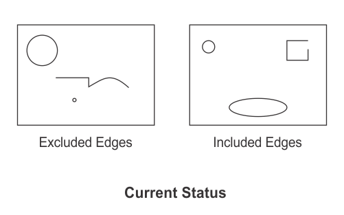
The edge labeled 5 is split into two edges at edgel 25. One edge consists of all edgels ranging from the start of edge 5 to the 24th edgel; this edge keeps the label 5 and is not selected for exclusion. The other edge consists of all edgels ranging from the 25th edgel to the end of edge 5; this edge gets a new label value and is selected for exclusion.
The edge labeled 3 is split into two edges at edgel 18. One edge consists of all edgels ranging from the start of edge 3 to the 18th edgel; this edge keeps the label 3 and is not selected for inclusion. The other edge consists of all edgels ranging from the 18th edgel to the end of edge 3; this edge gets a new label value and is selected for inclusion.
Advanced thresholding
Edge Finder uses a hysteresis thresholding method to perform the edge extraction. That is, edge chains are extracted such that the magnitude values of all connected edgels are stronger than the lower bound threshold value, and at least one edgel in each edge chain has a magnitude that is stronger than the upper bound threshold value. For more information on thresholding, and on setting these bounds, see the Thresholding subsection of the Customizing the edge extraction settings section earlier in this chapter.
Edge Finder also allows you to customize the behavior of the hysteresis thresholding using the MedgeControl() with M_THRESHOLD_TYPE. That is, M_THRESHOLD_TYPE allows you to set how the upper and lower bound threshold values will be used (as opposed to setting the bounds themselves).
If you set M_THRESHOLD_TYPE to M_HYSTERESIS, both the lower bound threshold value and the upper bound threshold value will be used. This is the default setting.
If you set M_THRESHOLD_TYPE to M_NO_HYSTERESIS, the lower bound threshold value is ignored, and is considered to be equal to the upper bound threshold value.
If you set M_THRESHOLD_TYPE to M_FULL_HYSTERESIS, only the upper bound threshold value is used; the lower bound threshold value is ignored, and is considered to be 0. In this case, the extracted edges are sets of connected edgels such that the magnitude of at least one edgel in each edge is stronger than the upper bound threshold value. This type of thresholding can be used to extract edges in noise-free highly multi-contrast images.
Providing the image's derivatives
Typically, you will let Edge Finder manage its own derivative images to perform the edge extraction. However, you can specify your own derivative image buffers, so that the edge extraction is done with them instead. In this case, when you call MedgeCalculate(), set the source image to M_NULL, and specify the required derivative image buffers instead. For example:
MedgeCalculate(MilEdgeContext, M_NULL, DerivX, DerivY, M_NULL,
               MilResult, M_DEFAULT);
Note that, when specifying your own derivative image buffers, the majority of the processing control settings remain in effect, except for filter settings (for example, M_FILTER_SMOOTHNESS).
Derivative image buffers must be 1-band 16-bit signed or 1-band 32-bit floating-point buffers. In addition, all derivative image buffers must be consistent (for example, they must have the same scaling factor), and they must be of the same type and size. When the derivative image buffers are 32-bit floating-point buffers, Edge Finder uses floating-point precision calculations.
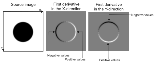
When extracting object contours, you must provide the image's first derivatives in both the X- and Y-directions. Note that the image derivatives must be consistent with the image axis; that is, if the intensity transition in the source image increases (from black to white) with the axis directions, the associated derivative values must be positive. Similarly, if the intensity transition in the source image decreases (from white to black) with the axis directions, the associated derivative values must be negative.
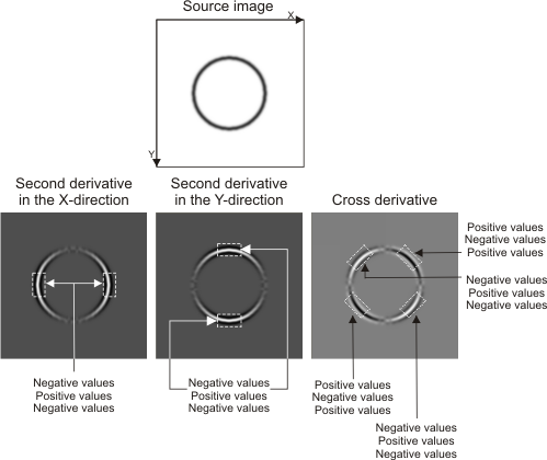
When extracting line crests, you must provide the image's second derivatives in both the X- and Y-direction, as well as the image's cross derivative. Note that the image derivatives must be consistent with the image axis; that is, a light line crest in the source image must result in negative second derivative values. Similarly, a dark line crest in the source image must result in positive second derivative values.
Putting data into an Edge Finder result buffer
Typically, you will use the Edge Finder result buffer to hold edge extraction information after an edge selection and calculation. However, Edge Finder also allows you to copy data from user-supplied arrays into an Edge Finder result buffer, using MedgePut(). This can be useful if you want to construct an Edge Finder result buffer that cannot be obtained from one image. You can therefore combine results from multiple Edge Finder result buffers to, for example, build a complete model to add to a Model Finder context. For more information, see the Defining and adding models to your Model Finder context section of Chapter 8: Geometric Model Finder.
Note that once edges are added to the Edge Finder result buffer, their features can be calculated with MedgeCalculate().
If edgels are calculated with pixel accuracy, you must provide edgels with coordinates that are integer values; in this case, the distance between consecutive edgels should be one pixel. If edgels are calculated with subpixel accuracy, you can provide edgels with coordinates that are double values; in this case, the distance between consecutive edgels is such that, each pixel touched by the edge corresponds to one edgel. To change the accuracy with which edgels are calculated, use MedgeControl() with M_ACCURACY.
To add data to an Edge Finder result buffer, you must use MedgePut() to specify the following user-supplied arrays:
You must also specify the number of edgels that you want to add to the Edge Finder result buffer. If necessary, you can also provide arrays containing the index of the edge each edgel belongs to, the orientation of the edgel and the magnitude of the edgel.
The information that you provide about the edges to add to the Edge Finder result buffer must be ordered on an edge by edge basis. For example, the following table illustrates how to supply X- and Y-coordinates for three distinct edges; note that the index provided is that of the edge each edgel belongs to:
|
Array of X-coordinates |
Array of Y-coordinates |
Array of edge indices |
|
1 |
2 |
1 |
|
2 |
3 |
1 |
|
2 |
4 |
1 |
|
3 |
3 |
1 |
|
1 |
9 |
2 |
|
2 |
9 |
2 |
|
2 |
8 |
2 |
|
4 |
6 |
3 |
|
5 |
6 |
3 |
Finding the closest edgels to a list of points
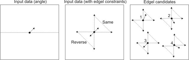
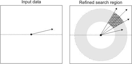
From an Edge Finder result buffer, you can retrieve the coordinates of edgels that correspond to the closest neighbors from a list of user-specified source point coordinates. You must use MedgeGetNeighbors() to specify your input data, which must include the source points and, if necessary, a corresponding angle for each point.
You can also set a series of constraints to which potential results (edgel candidates) must adhere before being returned. Only edgels that meet all constraints (if any are set) can be returned as the closest neighbors. To set the constraint(s), use MedgeControl().
You can either set simple constraints, advanced constraints, or both. Simple constraints are based on the location of the edgel candidate (the search region), while advanced constraints are typically based on the inner properties of the edgel candidate (the gradient angle).
When applying constraints, you should first set the ones based on location. This will establish the search region in the Edge Finder result buffer, and generate a group of edgel candidates. If you do not apply any edgel-based constraints, then the candidates in this region that are closest to the source points will be returned. However, if you set advanced constraints, then only the edgels in this region that also adhere to these constraints can be returned.
Advanced constraints are typically based on the source edgel's gradient angle. In this case, you must provide an angle value for each source point as part of your input data for MedgeGetNeighbors(). Therefore, the candidate edgel will only be returned if its gradient angle adheres to the constraint applied with the source angle. Note that an edgel's gradient angle is perpendicular to the edge, and is dependent on the edge extraction process. For more information on an edgel's gradient angle, see the How edges are calculated subsection of the Extracting the edges section earlier in this chapter.
Location-based constraints
You can use location-based constraints to limit the area within the Edge Finder result buffer from which edgels matching source points can be found. All edgels that do not fall within this area will be ignored. By default, the search region encompasses all edgels within the Edge Finder result buffer.
The following MedgeControl() control types can be used to specify location-based constraints:
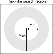
The maximum (M_SEARCH_RADIUS_MAX) and minimum (M_SEARCH_RADIUS_MIN) search radius constraints set the maximum and minimum distance radii in the Edge Finder result buffer that will be searched for the closest edgels. These values must be set in pixels. You must use MedgeGetNeighbors() to specify the source point from which the radii are measured.
Together, M_SEARCH_RADIUS_MAX and M_SEARCH_RADIUS_MIN define a ring-like region, in the Edge Finder result buffer, that will be used to find the closest edgels. All edgels that fall outside this ring will be ignored. By default, the minimum distance radius is 0 pixels, and the maximum distance radius is an infinite number of pixels (M_INFINITE); that is, by default, the entire Edge Finder result buffer will be searched. Note that the M_INFINITE setting will retrieve all the closest edgels (one edgel per edge).
The Edge Finder result buffer region that will be searched for the closest edgels can be further constrained to an angular sector within the area defined by the radius constraints (M_SEARCH_RADIUS_...). You can use M_SEARCH_ANGLE to define the search angle, and M_SEARCH_ANGLE_TOLERANCE to define the tolerance. The search angle is relative to the source angle set with MedgeGetNeighbors(), and the tolerance is applied to the resulting angle evenly; that is, half of the tolerance angle is applied in the positive direction, and half is applied in the negative direction. All edgels that are located within this angular sector (tolerance) can be returned. Any value between 0.0° to 360.0° can be set for both the search angle and tolerance. By default, M_SEARCH_ANGLE is set to 0.0° and M_SEARCH_ANGLE_TOLERANCE is set to 360.0 degrees; therefore, all edgels will be considered.
For example, if you set M_SEARCH_ANGLE to 30.0°, M_SEARCH_ANGLE_TOLERANCE to 30.0°, and the source angle to 15°, only edgels that fall between 30.0° and 60.0° will be considered.
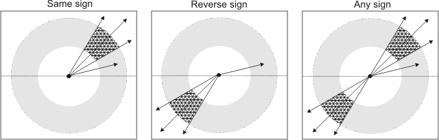
You can also set the sign of the angle that will be used to find the closest edgels with M_SEARCH_ANGLE_SIGN. The sign of the angle can be the same as (M_SAME) or the reverse of (M_REVERSE), the source angle set with MedgeGetNeighbors(). The default is M_SAME. The sign can also be set to M_SAME_OR_REVERSE, which means that it can be the same as, or the reverse of, the source angle.
For example, if you set the source angle to 15°, and the search angle and tolerance to 30.0°, then edgels that fall within an angle that has the same sign would be located between 30.0° and 60.0°, edgels that fall within an angle that has a reverse sign would be located between 210° and 240°, and edgels that fall within an angle that has any sign would be located at either between 30.0° and 60.0°, or between 210° and 240°.
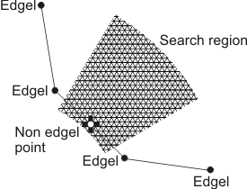
Note that, if necessary, you can allow a point between two edgels to be returned, using M_GET_SUBEDGELS in MedgeGetNeighbors(). In this case, an edgel candidate is returned, as long as an edge (and not necessarily an edgel) is located within the search region.
Edgel-based constraints
As mentioned, location-based constraints limit the region in the Edge Finder result buffer that will be searched for the closest edgels. Edgel-based constraints, on the other hand, are applied to the edgels themselves. Only edgels that adhere to these constraints can be returned. Note that, if you have applied location-based constraints, only edgels within the defined search region will be considered.
The following MedgeControl() control types are used to specify edgel-based constraints:
The maximum number constraint (M_NEIGHBOR_MAXIMUM_NUMBER) sets the maximum number of closest edgels (that is, the N closest edgels) that can be returned, for each source point. The default maximum number is 1; therefore, the edgel closest to each source point is returned.
The minimum spacing constraint (M_NEIGHBOR_MINIMUM_SPACING) sets the minimum distance separating closest edgel candidates within the same edge. Therefore, edgels that are too close together will not be returned. The spacing is set in number of edgels and must be greater than or equal to 1. The default minimum spacing is infinite (M_INFINITE), which means that there is no minimum distance (number of edgels) that must separate edgel candidates.
The neighbor's angle constraint (M_NEIGHBOR_ANGLE) sets the gradient angle that an edgel must have, before being considered a candidate. M_NEIGHBOR_ANGLE is based on a source angle (for each source point), set with MedgeGetNeighbors(). The gradient angle of the edgel candidate can be the same (M_SAME), the reverse (M_REVERSE), or the same or reverse (M_SAME_OR_REVERSE) as the angle of the source point. The constraint can also be set to any angle (M_ANY); in this case, the source angle and the source point are ignored. The default is M_ANY. Note that M_NEIGHBOR_ANGLE can only be used if the M_SAVE_ANGLE internal buffer was initially saved.
You can also set an angular tolerance for M_NEIGHBOR_ANGLE using M_NEIGHBOR_ANGLE_TOLERANCE. In this case, candidate edgels that have a gradient angle that falls within the specified angular range (tolerance) can be returned. The tolerance is applied to the M_NEIGHBOR_ANGLE value evenly; that is, half of the tolerance angle is applied in the positive direction, and half is applied in the negative direction. Any angle between 0.0° to 360.0° can be set as a tolerance. By default, M_NEIGHBOR_ANGLE_TOLERANCE is set to 180.0°; therefore, only candidate edgels that have a gradient angle that is the same as the source angle will be considered. Note that setting M_NEIGHBOR_ANGLE_TOLERANCE to 360.0° is equivalent to setting the neighbor angle constraint to M_ANY; in either case, edgels with any gradient angle are considered.
For example, if you set the angle of the source point to 45°, M_NEIGHBOR_ANGLE to M_SAME_OR_REVERSE, and M_NEIGHBOR_ANGLE_TOLERANCE to 90°, only edgels that have an angle between 0° and 90° or between 180° and 270° can be returned. In the following example, edgels 1 and 3 are considered the closest edgel candidates.