Defining and adding models to your Model Finder context
- See also

 Availability
 Previous
- Next

-
Model from an image.
-
Synthetic model.
-
Model from an Edge Finder or Model Finder result buffer.
-
Model created from two other models.
-
Define an empty image-type model, using MmodDefine() with M_AUTO_DEFINE set to M_NULL.
-
Set the model's settings, using MmodControl() with the index of the empty model.
-
Define a unique geometric model from the model source image using MmodControl() with M_AUTO_DEFINE and the identifier of the source image. MmodControl() searches for a model with unique geometric features in the model source image that takes into account the settings previously specified using MmodControl().
-
For an M_RECTANGLE or M_SEGMENT synthetic model defined in a shape-specific context (M_SHAPE_RECTANGLE or M_SHAPE_SEGMENT, respectively), you can specify to find occurrences that are not perfectly straight or are broken up. To specify the tolerance for deformation, use MmodControl() with M_DEVIATION_TOLERANCE. For more information on this control types, see the Deviation tolerance for rectangles and segments subsection of the Search settings specific to models in specialized shape contexts section later in this chapter.
-
For an M_CIRCLE synthetic model defined in an M_SHAPE_CIRCLE context, you can find occurrences that have deviation of the radii along the circumference of the model. For instance, an occurrence of a bottle cap could be identified as a circular model with the right radii deviation tolerance. You can control the radii deviation tolerance using M_SAGITTA_TOLERANCE. For more information regarding using this type of search constraint, see the Radii deviation tolerance subsection of the Search settings specific to models in specialized shape contexts section later in this chapter.
-
For an M_ELLIPSE synthetic model defined in an M_SHAPE_ELLIPSE context, you can find occurrences of the model that have varying aspect ratios (for example, due to the perspective). You should define the ellipse model (MmodDefine() with M_ELLIPSE) with the same width and height as that of the occurrence if the image had no distortion. If the image does have distortion that affects the occurrence's aspect ratio, you can use MmodControl() with M_MODEL_ASPECT_RATIO, M_MODEL_ASPECT_RATIO_MAX_FACTOR, and M_MODEL_ASPECT_RATIO_MIN_FACTOR to account for the expected aspect ratio difference. For more information on these control types, see the Aspect ratio and aspect ratio search constraint subsection of the Search settings specific to models in specialized shape contexts section later in this chapter.
-
The Edge Finder result buffer must have been previously allocated using MedgeAllocResult().
-
The Edge Finder result buffer must be compatible with the Model Finder context. Enable this using MedgeControl() with M_MODEL_FINDER_COMPATIBLE prior to calling MedgeCalculate().
-
You can speed up the time it takes to search for the models by setting M_EXTRACTION_SCALE in MedgeControl() prior to calling MedgeCalculate(). For more information, see the Interfacing with Geometric Model Finder section of Chapter 9: Edge Finder.
-
MedgeCalculate() must have been already called using this result buffer.
Once you have allocated a Model Finder context using MmodAlloc(), you can begin to add models to your Model Finder context.
There are four different kinds of models that can be added to a Model Finder context:
In general, all of these models can be mixed in the same Model Finder context, using MmodDefine() or MmodDefineFromFile(). The MmodDefine() function can add image-type models, result-type models, and predefined-shape synthetic models; the MmodDefineFromFile() function can add CAD-file synthetic models. If adding a model to a shape-specific Model Finder context, you can only add one model to it and it must be a synthetic model of the same type.
Image-type models
You can add models defined from an image to a Model Finder context manually or automatically, using MmodDefine() with M_IMAGE or M_AUTO_DEFINE, respectively. These types of models are referred to as image-type models.
The specified model source image must be a 1-band, 8-bit unsigned image.
When defining an image-type model manually, you must specify the region in the image from which to define the model. The minimum size of an image-type model is limited to 16.0 x 16.0 pixels, while the maximum size of 4096.0 x 4096.0 pixels is permitted. Note that image-type models are the only model type with a maximum permitted size of 4096.0 x 4096.0; all others have a maximum permitted size of 1024.0 x 1024.0.

To define an image-type model from a rotated region, you must specify an image that is associated to an ROI that was set using a rotated rectangle in a 2D graphics list. To add a rotated rectangle to a 2D graphics list, you can call MgraRectAngle(); to set (associate) that rectangle as the ROI of an image buffer, you can call MbufSetRegion() with M_RASTERIZE or M_NO_RASTERIZE and M_FILL_REGION.
When defining a model automatically, MIL searches the model source image for unique geometric features. When the most suitable geometric features are found, the function automatically defines a model from those features. To be useful, the model source image should be a typical target image; otherwise, the selected area for the model might never be present in the target. Defining a model automatically is useful, for example, when you want to perform whole image alignment, for which the displacement of a unique model from its original location specifies the displacement of the image. MIL can automatically define a model based on specified settings or on default settings. The former is useful if you know, for example, that the selected model needs to be non-ambiguous only in a small range of angles; its ambiguity needs not be checked for the entire default range. Note that MIL searches for the unique model far enough from the image borders so that if the target image is shifted from the model source image, the model can still be found; you specify the maximum displacement that can occur between the position of the model in the source image and the position of the model when found in the target image.
To define a model based on specified settings:
To define a model based on default settings, use MmodDefine() with M_AUTO_DEFINE and the identifier of the source image.
Extracting edges
When you call MmodDefine(), it stores the specified region of the model source image with the model. This image is referred to as the model image. The model source image is then no longer needed.
It is actually when you call MmodPreprocess() that edges are extracted from the model image. Specifically, MmodPreprocess() extracts the contour edges from the model image. For more information on contour edges, see the Extracting the edges section of Chapter 9: Edge Finder.
The edge extraction process involves a denoising operation to even out rough edges and reduce noise. You can control the degree of smoothness (strength) of the denoising operation used for all models in the context, using MmodControl() with M_SMOOTHNESS. The range of this control type varies from 0.0 to 100.0; a value of 100.0 results in a strong noise reduction effect, while a value of 0.0 has almost no noise reduction effect. The default setting is 50.0.

You can also control the detail level of the edge extraction process for all models in the context, using MmodControl() with M_DETAIL_LEVEL. Basically, this controls how much detail is extracted from the model image of each model in the context. The default setting (M_MEDIUM) offers a robust detection of edges from images with contrast variation, noise, and non-uniform illumination. Nevertheless, in cases where objects of interest have a very low contrast compared to high contrast areas in the image, some low contrast edges can be missed.
The following examples show the use of the M_DETAIL_LEVEL control type.

If your images contain low-contrast and high-contrast objects, and your object of interest is low-contrast, a detail level setting of M_HIGH should be used to ensure the detection of the low-contrast edges in the image. The M_VERY_HIGH setting performs an exhaustive edge extraction, including very low contrast edges. However, it should be noted that this setting is very sensitive to noise.
Generally, the default settings for M_SMOOTHNESS and M_DETAIL_LEVEL are sufficient for the majority of images; you should adjust these settings only when dealing with very noisy images, extremely low or multi-contrasted images, or images with very thin, refined features. In such cases, it is recommended that you experiment with different settings to achieve the necessary level of accuracy and speed required by your application.
Note that the settings for M_SMOOTHNESS and M_DETAIL_LEVEL are also applied to the search target when it is an image.
Synthetic models
Synthetic models are models that either have a predefined shape, or have been defined from a CAD DXF file. Synthetic models allow you to search the target for shapes.
Predefined-shape models
You can use MmodDefine() to add predefined-shape models to the context. The model types that are available are circle, cross, diamond, ellipse, rectangle, ring, square, and triangle. These model types are described in more detail in the description of MmodDefine().
Use the MmodDefine() parameters to define the attributes of the predefined-shape model, from the foreground color of the model to how it is constructed. The definition of each MmodDefine() parameter depends on the model. For example, for a circle model, MmodDefine() would have a parameter that defines the radius of the circle. For an ellipse model, MmodDefine() would have parameters that define the width and the height.
You can also round all the corners of a model that has corners (the cross, diamond, rectangle, square, and triangle models), except for one in a M_SHAPE_RECTANGLE context. Set the radius of the curvature for the model's corners using MmodControl() with M_CORNER_RADIUS.

Predefined-shape models use the center of the shape as the origin (0,0).
Predefined-shape models in specialized contexts
MIL has specialized shape-specific contexts to perform more robust searches for circles, ellipses, and rectangles. Using a specialized context, you can also search for segments. Even though these context types are dedicated to finding a particular shape, you must still add a model to the context, and it must be of the same type as the context. For these types of contexts, you can only add a single model to the context.
Use MmodDefine() as described above to add the model to the specialized shape-specific context. You can only add a synthetic segment model (M_SEGMENT) to an M_SHAPE_SEGMENT context. This allows you to search for occurrences of segments on contours of objects.

Note that if a line is found in the target, it is counted as two segment occurrences in opposite directions. To restrict it to a single occurrence, set MmodControl() with M_MIN_SEPARATION_ANGLE to M_DISABLE. See the Angle for rectangles and segments subsection of the Search settings specific to models in specialized shape contexts section later in this chapter.
Searching for a predefined-shape model using a shape-specific context has the following primary advantages:
CAD-file models
You can add models that are defined from CAD DXF files to a Model Finder context, using MmodDefineFromFile().
Not every entity in a CAD DXF file is supported; unsupported entities are ignored. The supported entities are Line, Polyline, Lwpolyline, Circle, Arc, Ellipse, Block (a collection of entities), and Insert (an entity containing a reference to where the Block should be drawn, and at what location and scale).
When the model is added to the Model Finder context from a CAD DXF file, the model will retain its coordinate system (the origin and the axis). Most CAD DXF files are oriented so that the Y-axis is positive going up, whereas the coordinate system MIL uses is oriented so that the Y-axis is positive going down. So if you take the edge coordinates of an object from a CAD DXF file and put them in an image, the imaged object will look flipped when compared to the original object. This is also the case for a model defined from a CAD DXF file. This means that, unless the object is symmetrical, the match will not be made. You can use MmodControl() with M_CAD_Y_AXIS to flip the Y-axis for the model so that it is positive going down.
Model size, units, and camera calibration when dealing with synthetic model in a geometric or geometric-controlled context
If adding a synthetic model to a M_GEOMETRIC or M_GEOMETRIC_CONTROLLED context, specify the model's dimensions in user-defined units. Specify the ratio between model units and pixel units using MmodControl() with M_PIXEL_SCALE.
If the target is not calibrated, M_PIXEL_SCALE is used for the match. If the target is calibrated, the model units should be the same as the calibrated units. If the target is calibrated, M_PIXEL_SCALE will be used for draw operations, but not for the match nor the returned results.
Note that if you are searching for a synthetic model in a calibrated target, you must also associate the camera calibration context of the target with the model, using M_ASSOCIATED_CALIBRATION. MIL needs the camera calibration context for internal purposes at preprocessing time. Note that MIL will not use the camera calibration context to compensate for incongruencies between the model and the target, nor will MIL map the model's coordinate system to that of the target.
After you have specified your pixel scale and scale settings, you can verify if your synthetic models are valid, using MmodInquire() with M_VALID. Synthetic models can be invalid if their global size in X or Y (size of the model box x M_PIXEL_SCALE x M_SCALE) is greater than 1024.
By default, synthetic models in a M_GEOMETRIC or M_GEOMETRIC_CONTROLLED context are defined to have a 10% margin around the bounding box of their active edges. When finding an occurrence, extra edges found in this area will reduce the target score. You can change the size of the margin using MmodControl() with the M_BOX_MARGIN_... control types.
Model size, units, and camera calibration when dealing with synthetic model in a shape-specific context
If adding a synthetic model to a M_SHAPE_... context, specify the model's dimensions in target units; the model is considered to have the same units as the target. If the target is calibrated, the model's dimensions and settings will be interpreted in world units. Conversely, if the target is not associated with a camera calibration context, the model's dimensions and settings will be interpreted in pixel units. The model will be defined in the same coordinate system as the target. You cannot associate a camera calibration context with the model in a M_SHAPE_... context.
By default, synthetic models are defined to have a 10% margin around the bounding box of their active edges. For a model in an M_SHAPE_... type of Model Finder context, this margin is only used for drawing; it does not affect the match. You can change the size of the margins using MmodControl() with the M_BOX_MARGIN_... control types.
Models defined from result buffers
You can define models from two different types of result buffers: Edge Finder result buffers and Model Finder result buffers. This allows you to use the edge map information in the result buffer to define the model.
In the case of these models, the model source image is the image from which the results were obtained. The model source is the result buffer in which the results are stored. The model image is a copy of the region in the model source image from which the model has been defined.
Models defined from an Edge Finder result buffer
You would define models from an Edge Finder result buffer if you want to use other types of edges, such as crest edges, or if you want to re-use the edge map for another purpose. If you know that the edges of interest have a minimum size, you could use Edge Finder to include only edges above that size. The included edges of the results are the ones that will be used to define the model. These result-type models are referred to as Edge Finder-type models.
Some things have to be done before you can define a model from an Edge Finder result buffer.
You can add models defined from an Edge Finder result buffer to a Model Finder context using MmodDefine() with M_EDGE_RESULT.
The size of the model can be defined using the offset and size parameters of MmodDefine().
Models defined from a Model Finder result buffer
Adding models defined from a Model Finder result buffer allows you to define new models from previous match occurrences. These models are referred to as Model Finder-type models.
There are many reasons to use a Model Finder-type model. For example, if you have a model that changes slightly over time, you can define a model from the result to update it. Updating the model prevents potentially misidentifying the model because it has changed beyond your starting tolerances.
To define a Model Finder-type model, use MmodDefine() with M_MOD_RESULT and pass the identifier of the Model Finder result buffer and the index of the occurrence to use. The model is defined with the edges of the target at the occurrence position. You have to use MmodControl() with M_MOD_DEFINE_COMPATIBLE enabled before you can use this feature; this must be done before MmodFind() finds the result. The result buffer must be compatible with the Model Finder context.
Models defined from two other models
Models can be defined from two previously existing models and added to the context. Use MmodDefine() with M_MERGE_MODEL and specify the two models from which to create the new model. The model will be formed by taking the first model specified and adding the edges of the second model that are not included in the edges of the first model.
There are no restrictions on the types of models you can merge. They can be of different types, as long as they are part of the same model context.
Preprocessing
After you add models to your context and before performing the search, you have to preprocess the context, using MmodPreprocess(), otherwise an error will occur. It does not matter the type of model, or the type of context. Calling MmodPreprocess() will prepare models for geometric matching. In the case of image-type models, it is also the time when edges are actually extracted from the model image.
Note that the Model Finder context must be preprocessed again if some of the models' search settings are changed. You can check if you need to preprocess after changing a control using MmodInquire() with M_PREPROCESSED.
When you save a Model Finder context, preprocessing information is not saved with the context. You must preprocess the context when the Model Finder context is restored.
Model origin
The model origin is the point in the model that is considered to be (0,0). The location of the model origin depends on the type of model: for image and Edge Finder-type models, the model origin is the center of the upper left pixel of the model image; for predefined-shape models, the center of the shape is the model origin. The model origin for a model defined from a CAD DXF file is the same as point (0,0) in the CAD DXF file.
Model indices and labels
Each model added to a Model Finder context can be accessed by its index. The first model is assigned an index of 0, and for each subsequent model added, the index is increased by one. You can also apply setting changes to all models within a Model Finder context using M_ALL as the index. When a model is deleted, all model indices greater than the deleted model are shifted down by one. MIL searches for all models within a context in parallel, therefore the model index does not have any bearing in terms of a search order.
Models can also be given a user-defined numeric label, using MmodControl() with M_USER_LABEL. A user label can be used as a means of identifying your model, independently from its index in the Model Finder context. However, user labels cannot be used as a direct replacement for the index; to retrieve the index of a model from the user label, use MmodInquire() with M_INDEX_FROM_LABEL. The user label, once converted to an index value, can be used with any Mmod...() function that takes an index value. All user labels must be unique integers; that is, no two user labels can have the same integer. To remove a label from a model, set the user label to M_NO_LABEL.
Drawing and inquiring the model's active edges
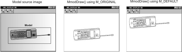
When testing different model source images for the best model candidate, you can use MmodDraw() to draw the model's active edges. This can be done for any type of model, although for synthetic models it is less useful, since the edges should already be known. The resulting edge map can reveal whether the edges you have chosen are the ones that you want, or if there are problems with the edges. You can use MmodInquire() with the M_ALLOC_SIZE... inquire types to determine the necessary size for the destination image buffer. To make corrections for image-type or Model Finder-type models, you might have to adjust the image processing control types, or mask unwanted edges. For Edge Finder-type models, you can exclude edges that you don't want from the Edge Finder result buffer and redefine the model, or you can mask unwanted edges.
If you have used offsets to define the model region in the model source, you can draw the active edges at the position where the model was defined using MmodDraw() with M_ORIGINAL; otherwise the active edges will be drawn at the center of the top-left pixel of the destination image. This is valid for image-type or Edge Finder-type models.
You can use MmodInquire() with the M_CHAIN_INDEX, M_CHAIN_X, and M_CHAIN_Y controls to inquire the active edges of the model.
Note that if you try to draw a model's edges and its Model Finder context has not been preprocessed, a preliminary edge extraction operation will be performed for the model.
You can also draw features from a zoomed region of the model image, as well as other items. To do so, specify the appropriate values for the MgraControl() M_DRAW_OFFSET_X, M_DRAW_OFFSET_Y, M_DRAW_ZOOM_X, and M_DRAW_ZOOM_Y control types. The relative origin values must be specified in pixels, and are relative to the coordinates of the top-left corner of the region in the model image, while the scale values specify the X- and Y-scaling factors used to fill the destination image buffer.
