Matrox Rapixo CXP connectors and signal names
- See also

 Previous
- Next

This section serves as a reference to match Matrox Rapixo CXP's connectors and auxiliary signals with MIL information, such as MIL auxiliary signal numbers. To set/inquire all the settings for this board's auxiliary signals (for example, signal routing and timer settings), use MdigControl() / MdigInquire(), respectively.
On Matrox Rapixo CXP, the auxiliary signals are acquisition path independent. Any digitizer allocated on the board (M_DEV0 through M_DEV3) can access any of the auxiliary signals.
Auxiliary I/O signals can have one or more functionalities (for example, trigger input, timer output, or user output, depending on the signal). Their possible functionalities are described in their description in the pinout table below. Note that, unlike some other Matrox frame grabbers, there is no limit to the number of events that can be triggered simultaneously using the auxiliary input signals, nor is there a restriction on which auxiliary signal can be used to trigger the event.
Only those auxiliary signals that have matching MIL information are included in this section. For information on internal connectors and a comprehensive list of all available input and output signals, refer to the board's installation and hardware reference manual.
Board connectors
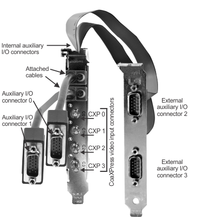
The Matrox Rapixo CXP board provides two interface options: the mDP-to-HD15 adapter cable or the HD-15 cable adapter bracket. On the mDP-to-HD15 adapter cables, which connect to the main bracket, there are two external auxiliary I/O connectors. On the cable adapter bracket, there are two external auxiliary I/O connectors.
Only the following connectors have auxiliary signals with matching MIL information.
|
Connector Name |
Connector Abbreviation |
Image |
Description |
|
External auxiliary I/O connectors |
HD-15 (0, 1, 2 and 3) |
|
The external auxiliary I/O connectors are high-density D-subminiature 15-pin male connectors. They are used to transmit/receive auxiliary signals. External auxiliary I/O connector 0 and 1 are located on the mDP-to-HD15 adapter cables, and external auxiliary I/O connectors 2 and 3 are located on the cable adapter bracket. |
Signal names and their matching MIL constants
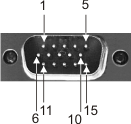
The table below lists the auxiliary signals with their associated MIL information. The pinout for auxiliary I/O connector 0 is as follows. Auxiliary I/O connectors 1, 2, and 3 have the same pinout as auxiliary I/O connector 0, except you must add 8, 16, or 24, respectively, to the number at the end of their hardware signal name and MIL constant. For example, AUX(TRIG)_TTL_IO_4 ( M_AUX_IO4 ) on connector 0 would be AUX(TRIG)_TTL_IO_12 ( M_AUX_IO12 ) on connector 1.
|
|
Description | ||
| MIL I/O # | |||
| Pin information | |||
| Direction | |||
| User-bit information | |||
| Trigger information | |||
| Timer information | |||
| Hardware manual signal name | |||
|
Indicates the following. (summarize)Indicates the following. (more details...) |
|||
|
Opto-isolated auziliary signal 0 (input), which supports: trigger input or user input. (summarize)Opto-isolated auziliary signal 0 (input), which supports: trigger input or user input. (more details...) |
|||
| Pin information | Connector: HD-15 (0) Pin: 15+, 9- | ||
| Direction |
Input |
||
| Trigger information |
Trigger
controller selected automatically.
Trigger shared between acq paths. 1
M_HARDWARE_PORT0;
Digitizer device #: M_DEVn 1 ;
|
||
| Hardware manual signal name | AUX(TRIG)_OPTO_IN0 | ||
|
Opto-isolated auxiliary signal 1 (input), which supports: trigger input or user input. (summarize)Opto-isolated auxiliary signal 1 (input), which supports: trigger input or user input. (more details...) |
|||
| Pin information | Connector: HD-15 (0) Pin: 12+, 11- | ||
| Direction |
Input |
||
| Trigger information |
Trigger
controller selected automatically.
Trigger shared between acq paths. 1
M_HARDWARE_PORT1;
Digitizer device #: M_DEVn 1 ;
|
||
| Hardware manual signal name | AUX(TRIG)_OPTO_IN1 | ||
|
LVDS auxiliary signal 2 (input), which supports: trigger input, user input, or quadrature input bit 0. (summarize)LVDS auxiliary signal 2 (input), which supports: trigger input, user input, or quadrature input bit 0. (more details...) |
|||
| Pin information | Connector: HD-15 (0) Pin: 4+, 5- | ||
| Direction |
Input |
||
| Trigger information |
Trigger
controller selected automatically.
Trigger shared between acq paths. 1
M_HARDWARE_PORT2;
Digitizer device #: M_DEVn 1 ;
|
||
| Hardware manual signal name | AUX(TRIG)_LVDS_IN2 | ||
|
LVDS auxiliary signal 3 (input), which supports: trigger input, user input, or quadrature input bit 1. (summarize)LVDS auxiliary signal 3 (input), which supports: trigger input, user input, or quadrature input bit 1. (more details...) |
|||
| Pin information | Connector: HD-15 (0) Pin: 6+, 8- | ||
| Direction |
Input |
||
| Trigger information |
Trigger
controller selected automatically.
Trigger shared between acq paths. 1
M_HARDWARE_PORT3;
Digitizer device #: M_DEVn 1 ;
|
||
| Hardware manual signal name | AUX(TRIG)_LVDS_IN3 | ||
|
TTL auxiliary signal 4 (input/output), which supports: timer output, trigger input, user input, or user output. (summarize)TTL auxiliary signal 4 (input/output), which supports: timer output, trigger input, user input, or user output. (more details...) |
|||
| Pin information | Connector: HD-15 (0) Pin: 1+ | ||
| Direction |
Input/Output |
||
| User-bit information |
MIL user-bit #: M_USER_BIT4;
Digitizer device #: M_DEVn 1 ;
|
||
| Trigger information |
Trigger
controller selected automatically.
Trigger shared between acq paths. 1
M_HARDWARE_PORT4;
Digitizer device #: M_DEVn 1 ;
|
||
| Timer information | Timer: M_TIMER1/M_TIMER2/M_TIMER3/M_TIMER4; Digitizer device #: M_DEVn 1 ; | ||
| Hardware manual signal name | AUX(TRIG)_TTL_IO_4 | ||
|
TTL auxiliary signal 5 (input/output), which supports: timer output, trigger input, user input, or user output. (summarize)TTL auxiliary signal 5 (input/output), which supports: timer output, trigger input, user input, or user output. (more details...) |
|||
| Pin information | Connector: HD-15 (0) Pin: 2+ | ||
| Direction |
Input/Output |
||
| User-bit information |
MIL user-bit #: M_USER_BIT5;
Digitizer device #: M_DEVn 1 ;
|
||
| Trigger information |
Trigger
controller selected automatically.
Trigger shared between acq paths. 1
M_HARDWARE_PORT5;
Digitizer device #: M_DEVn 1 ;
|
||
| Timer information | Timer: M_TIMER1/M_TIMER2/M_TIMER3/M_TIMER4; Digitizer device #: M_DEVn 1 ; | ||
| Hardware manual signal name | AUX(TRIG)_TTL_IO_5 | ||
|
TTL auxiliary signal 6 (input/output), which supports: timer output, trigger input, user input, or user output. (summarize)TTL auxiliary signal 6 (input/output), which supports: timer output, trigger input, user input, or user output. (more details...) |
|||
| Pin information | Connector: HD-15 (0) Pin: 3+ | ||
| Direction |
Input/Output |
||
| User-bit information |
MIL user-bit #: M_USER_BIT6;
Digitizer device #: M_DEVn 1 ;
|
||
| Trigger information |
Trigger
controller selected automatically.
Trigger shared between acq paths. 1
M_HARDWARE_PORT6;
Digitizer device #: M_DEVn 1 ;
|
||
| Timer information | Timer: M_TIMER1/M_TIMER2/M_TIMER3/M_TIMER4; Digitizer device #: M_DEVn 1 ; | ||
| Hardware manual signal name | AUX(TRIG)_TTL_IO_6 | ||
|
LVDS auxiliary signal 7 (output), which supports: timer output or user output. (summarize)LVDS auxiliary signal 7 (output), which supports: timer output or user output. (more details...) |
|||
| Pin information | Connector: HD-15 (0) Pin: 13+, 14- | ||
| Direction |
Output |
||
| User-bit information |
MIL user-bit #: M_USER_BIT7;
Digitizer device #: M_DEVn 1 ;
|
||
| Timer information | Timer: M_TIMER1/M_TIMER2/M_TIMER3/M_TIMER4; Digitizer device #: M_DEVn 1 ; | ||
| Hardware manual signal name | AUX(EXP)_LVDS_OUT7 | ||
|
|
Description | ||
| MIL I/O # | |||
| Pin information | |||
| Direction | |||
| User-bit information | |||
| Trigger information | |||
| Timer information | |||
| Hardware manual signal name | |||
|
Indicates the following. (summarize)Indicates the following. (more details...) |
|||
|
Opto-isolated auziliary signal 0 (input), which supports: trigger input or user input. (summarize)Opto-isolated auziliary signal 0 (input), which supports: trigger input or user input. (more details...) |
|||
| Pin information | Connector: HD-15 (0) Pin: 15+, 9- | ||
| Direction |
Input |
||
| Trigger information |
Trigger
controller selected automatically.
Trigger shared between acq paths. 1
M_HARDWARE_PORT0;
Digitizer device #: M_DEVn 1 ;
|
||
| Hardware manual signal name | AUX(TRIG)_OPTO_IN0 | ||
|
Opto-isolated auxiliary signal 1 (input), which supports: trigger input or user input. (summarize)Opto-isolated auxiliary signal 1 (input), which supports: trigger input or user input. (more details...) |
|||
| Pin information | Connector: HD-15 (0) Pin: 12+, 11- | ||
| Direction |
Input |
||
| Trigger information |
Trigger
controller selected automatically.
Trigger shared between acq paths. 1
M_HARDWARE_PORT1;
Digitizer device #: M_DEVn 1 ;
|
||
| Hardware manual signal name | AUX(TRIG)_OPTO_IN1 | ||
|
LVDS auxiliary signal 2 (input), which supports: trigger input, user input, or quadrature input bit 0. (summarize)LVDS auxiliary signal 2 (input), which supports: trigger input, user input, or quadrature input bit 0. (more details...) |
|||
| Pin information | Connector: HD-15 (0) Pin: 4+, 5- | ||
| Direction |
Input |
||
| Trigger information |
Trigger
controller selected automatically.
Trigger shared between acq paths. 1
M_HARDWARE_PORT2;
Digitizer device #: M_DEVn 1 ;
|
||
| Hardware manual signal name | AUX(TRIG)_LVDS_IN2 | ||
|
LVDS auxiliary signal 3 (input), which supports: trigger input, user input, or quadrature input bit 1. (summarize)LVDS auxiliary signal 3 (input), which supports: trigger input, user input, or quadrature input bit 1. (more details...) |
|||
| Pin information | Connector: HD-15 (0) Pin: 6+, 8- | ||
| Direction |
Input |
||
| Trigger information |
Trigger
controller selected automatically.
Trigger shared between acq paths. 1
M_HARDWARE_PORT3;
Digitizer device #: M_DEVn 1 ;
|
||
| Hardware manual signal name | AUX(TRIG)_LVDS_IN3 | ||
|
TTL auxiliary signal 4 (input/output), which supports: timer output, trigger input, user input, or user output. (summarize)TTL auxiliary signal 4 (input/output), which supports: timer output, trigger input, user input, or user output. (more details...) |
|||
| Pin information | Connector: HD-15 (0) Pin: 1+ | ||
| Direction |
Input/Output |
||
| User-bit information |
MIL user-bit #: M_USER_BIT4;
Digitizer device #: M_DEVn 1 ;
|
||
| Trigger information |
Trigger
controller selected automatically.
Trigger shared between acq paths. 1
M_HARDWARE_PORT4;
Digitizer device #: M_DEVn 1 ;
|
||
| Timer information | Timer: M_TIMER1/M_TIMER2/M_TIMER3/M_TIMER4; Digitizer device #: M_DEVn 1 ; | ||
| Hardware manual signal name | AUX(TRIG)_TTL_IO_4 | ||
|
TTL auxiliary signal 5 (input/output), which supports: timer output, trigger input, user input, or user output. (summarize)TTL auxiliary signal 5 (input/output), which supports: timer output, trigger input, user input, or user output. (more details...) |
|||
| Pin information | Connector: HD-15 (0) Pin: 2+ | ||
| Direction |
Input/Output |
||
| User-bit information |
MIL user-bit #: M_USER_BIT5;
Digitizer device #: M_DEVn 1 ;
|
||
| Trigger information |
Trigger
controller selected automatically.
Trigger shared between acq paths. 1
M_HARDWARE_PORT5;
Digitizer device #: M_DEVn 1 ;
|
||
| Timer information | Timer: M_TIMER1/M_TIMER2/M_TIMER3/M_TIMER4; Digitizer device #: M_DEVn 1 ; | ||
| Hardware manual signal name | AUX(TRIG)_TTL_IO_5 | ||
|
TTL auxiliary signal 6 (input/output), which supports: timer output, trigger input, user input, or user output. (summarize)TTL auxiliary signal 6 (input/output), which supports: timer output, trigger input, user input, or user output. (more details...) |
|||
| Pin information | Connector: HD-15 (0) Pin: 3+ | ||
| Direction |
Input/Output |
||
| User-bit information |
MIL user-bit #: M_USER_BIT6;
Digitizer device #: M_DEVn 1 ;
|
||
| Trigger information |
Trigger
controller selected automatically.
Trigger shared between acq paths. 1
M_HARDWARE_PORT6;
Digitizer device #: M_DEVn 1 ;
|
||
| Timer information | Timer: M_TIMER1/M_TIMER2/M_TIMER3/M_TIMER4; Digitizer device #: M_DEVn 1 ; | ||
| Hardware manual signal name | AUX(TRIG)_TTL_IO_6 | ||
|
|
Description | ||
| MIL I/O # | |||
| Pin information | |||
| Direction | |||
| User-bit information | |||
| Trigger information | |||
| Timer information | |||
| Hardware manual signal name | |||
|
Indicates the following. (summarize)Indicates the following. (more details...) |
|||
|
TTL auxiliary signal 4 (input/output), which supports: timer output, trigger input, user input, or user output. (summarize)TTL auxiliary signal 4 (input/output), which supports: timer output, trigger input, user input, or user output. (more details...) |
|||
| Pin information | Connector: HD-15 (0) Pin: 1+ | ||
| Direction |
Input/Output |
||
| User-bit information |
MIL user-bit #: M_USER_BIT4;
Digitizer device #: M_DEVn 1 ;
|
||
| Trigger information |
Trigger
controller selected automatically.
Trigger shared between acq paths. 1
M_HARDWARE_PORT4;
Digitizer device #: M_DEVn 1 ;
|
||
| Timer information | Timer: M_TIMER1/M_TIMER2/M_TIMER3/M_TIMER4; Digitizer device #: M_DEVn 1 ; | ||
| Hardware manual signal name | AUX(TRIG)_TTL_IO_4 | ||
|
TTL auxiliary signal 5 (input/output), which supports: timer output, trigger input, user input, or user output. (summarize)TTL auxiliary signal 5 (input/output), which supports: timer output, trigger input, user input, or user output. (more details...) |
|||
| Pin information | Connector: HD-15 (0) Pin: 2+ | ||
| Direction |
Input/Output |
||
| User-bit information |
MIL user-bit #: M_USER_BIT5;
Digitizer device #: M_DEVn 1 ;
|
||
| Trigger information |
Trigger
controller selected automatically.
Trigger shared between acq paths. 1
M_HARDWARE_PORT5;
Digitizer device #: M_DEVn 1 ;
|
||
| Timer information | Timer: M_TIMER1/M_TIMER2/M_TIMER3/M_TIMER4; Digitizer device #: M_DEVn 1 ; | ||
| Hardware manual signal name | AUX(TRIG)_TTL_IO_5 | ||
|
TTL auxiliary signal 6 (input/output), which supports: timer output, trigger input, user input, or user output. (summarize)TTL auxiliary signal 6 (input/output), which supports: timer output, trigger input, user input, or user output. (more details...) |
|||
| Pin information | Connector: HD-15 (0) Pin: 3+ | ||
| Direction |
Input/Output |
||
| User-bit information |
MIL user-bit #: M_USER_BIT6;
Digitizer device #: M_DEVn 1 ;
|
||
| Trigger information |
Trigger
controller selected automatically.
Trigger shared between acq paths. 1
M_HARDWARE_PORT6;
Digitizer device #: M_DEVn 1 ;
|
||
| Timer information | Timer: M_TIMER1/M_TIMER2/M_TIMER3/M_TIMER4; Digitizer device #: M_DEVn 1 ; | ||
| Hardware manual signal name | AUX(TRIG)_TTL_IO_6 | ||
|
LVDS auxiliary signal 7 (output), which supports: timer output or user output. (summarize)LVDS auxiliary signal 7 (output), which supports: timer output or user output. (more details...) |
|||
| Pin information | Connector: HD-15 (0) Pin: 13+, 14- | ||
| Direction |
Output |
||
| User-bit information |
MIL user-bit #: M_USER_BIT7;
Digitizer device #: M_DEVn 1 ;
|
||
| Timer information | Timer: M_TIMER1/M_TIMER2/M_TIMER3/M_TIMER4; Digitizer device #: M_DEVn 1 ; | ||
| Hardware manual signal name | AUX(EXP)_LVDS_OUT7 | ||
|
|
Description | ||
| MIL I/O # | |||
| Pin information | |||
| Direction | |||
| User-bit information | |||
| Trigger information | |||
| Timer information | |||
| Hardware manual signal name | |||
|
Indicates the following. (summarize)Indicates the following. (more details...) |
|||
|
TTL auxiliary signal 4 (input/output), which supports: timer output, trigger input, user input, or user output. (summarize)TTL auxiliary signal 4 (input/output), which supports: timer output, trigger input, user input, or user output. (more details...) |
|||
| Pin information | Connector: HD-15 (0) Pin: 1+ | ||
| Direction |
Input/Output |
||
| User-bit information |
MIL user-bit #: M_USER_BIT4;
Digitizer device #: M_DEVn 1 ;
|
||
| Trigger information |
Trigger
controller selected automatically.
Trigger shared between acq paths. 1
M_HARDWARE_PORT4;
Digitizer device #: M_DEVn 1 ;
|
||
| Timer information | Timer: M_TIMER1/M_TIMER2/M_TIMER3/M_TIMER4; Digitizer device #: M_DEVn 1 ; | ||
| Hardware manual signal name | AUX(TRIG)_TTL_IO_4 | ||
|
TTL auxiliary signal 5 (input/output), which supports: timer output, trigger input, user input, or user output. (summarize)TTL auxiliary signal 5 (input/output), which supports: timer output, trigger input, user input, or user output. (more details...) |
|||
| Pin information | Connector: HD-15 (0) Pin: 2+ | ||
| Direction |
Input/Output |
||
| User-bit information |
MIL user-bit #: M_USER_BIT5;
Digitizer device #: M_DEVn 1 ;
|
||
| Trigger information |
Trigger
controller selected automatically.
Trigger shared between acq paths. 1
M_HARDWARE_PORT5;
Digitizer device #: M_DEVn 1 ;
|
||
| Timer information | Timer: M_TIMER1/M_TIMER2/M_TIMER3/M_TIMER4; Digitizer device #: M_DEVn 1 ; | ||
| Hardware manual signal name | AUX(TRIG)_TTL_IO_5 | ||
|
TTL auxiliary signal 6 (input/output), which supports: timer output, trigger input, user input, or user output. (summarize)TTL auxiliary signal 6 (input/output), which supports: timer output, trigger input, user input, or user output. (more details...) |
|||
| Pin information | Connector: HD-15 (0) Pin: 3+ | ||
| Direction |
Input/Output |
||
| User-bit information |
MIL user-bit #: M_USER_BIT6;
Digitizer device #: M_DEVn 1 ;
|
||
| Trigger information |
Trigger
controller selected automatically.
Trigger shared between acq paths. 1
M_HARDWARE_PORT6;
Digitizer device #: M_DEVn 1 ;
|
||
| Timer information | Timer: M_TIMER1/M_TIMER2/M_TIMER3/M_TIMER4; Digitizer device #: M_DEVn 1 ; | ||
| Hardware manual signal name | AUX(TRIG)_TTL_IO_6 | ||
|
|
Description | ||
| MIL I/O # | |||
| Pin information | |||
| Direction | |||
| User-bit information | |||
| Trigger information | |||
| Timer information | |||
| Hardware manual signal name | |||
|
Indicates the following. (summarize)Indicates the following. (more details...) |
|||
|
TTL auxiliary signal 4 (input/output), which supports: timer output, trigger input, user input, or user output. (summarize)TTL auxiliary signal 4 (input/output), which supports: timer output, trigger input, user input, or user output. (more details...) |
|||
| Pin information | Connector: HD-15 (0) Pin: 1+ | ||
| Direction |
Input/Output |
||
| User-bit information |
MIL user-bit #: M_USER_BIT4;
Digitizer device #: M_DEVn 1 ;
|
||
| Trigger information |
Trigger
controller selected automatically.
Trigger shared between acq paths. 1
M_HARDWARE_PORT4;
Digitizer device #: M_DEVn 1 ;
|
||
| Timer information | Timer: M_TIMER1/M_TIMER2/M_TIMER3/M_TIMER4; Digitizer device #: M_DEVn 1 ; | ||
| Hardware manual signal name | AUX(TRIG)_TTL_IO_4 | ||
|
TTL auxiliary signal 5 (input/output), which supports: timer output, trigger input, user input, or user output. (summarize)TTL auxiliary signal 5 (input/output), which supports: timer output, trigger input, user input, or user output. (more details...) |
|||
| Pin information | Connector: HD-15 (0) Pin: 2+ | ||
| Direction |
Input/Output |
||
| User-bit information |
MIL user-bit #: M_USER_BIT5;
Digitizer device #: M_DEVn 1 ;
|
||
| Trigger information |
Trigger
controller selected automatically.
Trigger shared between acq paths. 1
M_HARDWARE_PORT5;
Digitizer device #: M_DEVn 1 ;
|
||
| Timer information | Timer: M_TIMER1/M_TIMER2/M_TIMER3/M_TIMER4; Digitizer device #: M_DEVn 1 ; | ||
| Hardware manual signal name | AUX(TRIG)_TTL_IO_5 | ||
|
TTL auxiliary signal 6 (input/output), which supports: timer output, trigger input, user input, or user output. (summarize)TTL auxiliary signal 6 (input/output), which supports: timer output, trigger input, user input, or user output. (more details...) |
|||
| Pin information | Connector: HD-15 (0) Pin: 3+ | ||
| Direction |
Input/Output |
||
| User-bit information |
MIL user-bit #: M_USER_BIT6;
Digitizer device #: M_DEVn 1 ;
|
||
| Trigger information |
Trigger
controller selected automatically.
Trigger shared between acq paths. 1
M_HARDWARE_PORT6;
Digitizer device #: M_DEVn 1 ;
|
||
| Timer information | Timer: M_TIMER1/M_TIMER2/M_TIMER3/M_TIMER4; Digitizer device #: M_DEVn 1 ; | ||
| Hardware manual signal name | AUX(TRIG)_TTL_IO_6 | ||
|
LVDS auxiliary signal 7 (output), which supports: timer output or user output. (summarize)LVDS auxiliary signal 7 (output), which supports: timer output or user output. (more details...) |
|||
| Pin information | Connector: HD-15 (0) Pin: 13+, 14- | ||
| Direction |
Output |
||
| User-bit information |
MIL user-bit #: M_USER_BIT7;
Digitizer device #: M_DEVn 1 ;
|
||
| Timer information | Timer: M_TIMER1/M_TIMER2/M_TIMER3/M_TIMER4; Digitizer device #: M_DEVn 1 ; | ||
| Hardware manual signal name | AUX(EXP)_LVDS_OUT7 | ||
|
|
Description | ||
| MIL I/O # | |||
| Pin information | |||
| Direction | |||
| User-bit information | |||
| Trigger information | |||
| Timer information | |||
| Hardware manual signal name | |||
|
Indicates the following. (summarize)Indicates the following. (more details...) |
|||
|
Opto-isolated auziliary signal 0 (input), which supports: trigger input or user input. (summarize)Opto-isolated auziliary signal 0 (input), which supports: trigger input or user input. (more details...) |
|||
| Pin information | Connector: HD-15 (0) Pin: 15+, 9- | ||
| Direction |
Input |
||
| Trigger information |
Trigger
controller selected automatically.
Trigger shared between acq paths. 1
M_HARDWARE_PORT0;
Digitizer device #: M_DEVn 1 ;
|
||
| Hardware manual signal name | AUX(TRIG)_OPTO_IN0 | ||
|
Opto-isolated auxiliary signal 1 (input), which supports: trigger input or user input. (summarize)Opto-isolated auxiliary signal 1 (input), which supports: trigger input or user input. (more details...) |
|||
| Pin information | Connector: HD-15 (0) Pin: 12+, 11- | ||
| Direction |
Input |
||
| Trigger information |
Trigger
controller selected automatically.
Trigger shared between acq paths. 1
M_HARDWARE_PORT1;
Digitizer device #: M_DEVn 1 ;
|
||
| Hardware manual signal name | AUX(TRIG)_OPTO_IN1 | ||
|
LVDS auxiliary signal 2 (input), which supports: trigger input, user input, or quadrature input bit 0. (summarize)LVDS auxiliary signal 2 (input), which supports: trigger input, user input, or quadrature input bit 0. (more details...) |
|||
| Pin information | Connector: HD-15 (0) Pin: 4+, 5- | ||
| Direction |
Input |
||
| Trigger information |
Trigger
controller selected automatically.
Trigger shared between acq paths. 1
M_HARDWARE_PORT2;
Digitizer device #: M_DEVn 1 ;
|
||
| Hardware manual signal name | AUX(TRIG)_LVDS_IN2 | ||
|
LVDS auxiliary signal 3 (input), which supports: trigger input, user input, or quadrature input bit 1. (summarize)LVDS auxiliary signal 3 (input), which supports: trigger input, user input, or quadrature input bit 1. (more details...) |
|||
| Pin information | Connector: HD-15 (0) Pin: 6+, 8- | ||
| Direction |
Input |
||
| Trigger information |
Trigger
controller selected automatically.
Trigger shared between acq paths. 1
M_HARDWARE_PORT3;
Digitizer device #: M_DEVn 1 ;
|
||
| Hardware manual signal name | AUX(TRIG)_LVDS_IN3 | ||
|
TTL auxiliary signal 4 (input/output), which supports: timer output, trigger input, user input, or user output. (summarize)TTL auxiliary signal 4 (input/output), which supports: timer output, trigger input, user input, or user output. (more details...) |
|||
| Pin information | Connector: HD-15 (0) Pin: 1+ | ||
| Direction |
Input/Output |
||
| User-bit information |
MIL user-bit #: M_USER_BIT4;
Digitizer device #: M_DEVn 1 ;
|
||
| Trigger information |
Trigger
controller selected automatically.
Trigger shared between acq paths. 1
M_HARDWARE_PORT4;
Digitizer device #: M_DEVn 1 ;
|
||
| Timer information | Timer: M_TIMER1/M_TIMER2/M_TIMER3/M_TIMER4; Digitizer device #: M_DEVn 1 ; | ||
| Hardware manual signal name | AUX(TRIG)_TTL_IO_4 | ||
|
TTL auxiliary signal 5 (input/output), which supports: timer output, trigger input, user input, or user output. (summarize)TTL auxiliary signal 5 (input/output), which supports: timer output, trigger input, user input, or user output. (more details...) |
|||
| Pin information | Connector: HD-15 (0) Pin: 2+ | ||
| Direction |
Input/Output |
||
| User-bit information |
MIL user-bit #: M_USER_BIT5;
Digitizer device #: M_DEVn 1 ;
|
||
| Trigger information |
Trigger
controller selected automatically.
Trigger shared between acq paths. 1
M_HARDWARE_PORT5;
Digitizer device #: M_DEVn 1 ;
|
||
| Timer information | Timer: M_TIMER1/M_TIMER2/M_TIMER3/M_TIMER4; Digitizer device #: M_DEVn 1 ; | ||
| Hardware manual signal name | AUX(TRIG)_TTL_IO_5 | ||
|
TTL auxiliary signal 6 (input/output), which supports: timer output, trigger input, user input, or user output. (summarize)TTL auxiliary signal 6 (input/output), which supports: timer output, trigger input, user input, or user output. (more details...) |
|||
| Pin information | Connector: HD-15 (0) Pin: 3+ | ||
| Direction |
Input/Output |
||
| User-bit information |
MIL user-bit #: M_USER_BIT6;
Digitizer device #: M_DEVn 1 ;
|
||
| Trigger information |
Trigger
controller selected automatically.
Trigger shared between acq paths. 1
M_HARDWARE_PORT6;
Digitizer device #: M_DEVn 1 ;
|
||
| Timer information | Timer: M_TIMER1/M_TIMER2/M_TIMER3/M_TIMER4; Digitizer device #: M_DEVn 1 ; | ||
| Hardware manual signal name | AUX(TRIG)_TTL_IO_6 | ||
|
|
Description | ||
| Pin | |||
| MIL I/O information | |||
| Direction | |||
| User-bit information | |||
| Trigger information | |||
| Timer information | |||
| Hardware manual signal name | |||
|
Indicates the following. (summarize)Indicates the following. (more details...) |
|||
|
TTL auxiliary signal 4 (input/output), which supports: timer output, trigger input, user input, or user output. (summarize)TTL auxiliary signal 4 (input/output), which supports: timer output, trigger input, user input, or user output. (more details...) |
|||
| MIL I/O information | MIL I/O #:M_AUX_IO4;
Digitizer device #: M_DEVn 1 ;
|
||
| Direction |
Input/Output |
||
| User-bit information |
MIL user-bit #: M_USER_BIT4;
Digitizer device #: M_DEVn 1 ;
|
||
| Trigger information |
Trigger
controller selected automatically.
Trigger shared between acq paths. 1
M_HARDWARE_PORT4;
Digitizer device #: M_DEVn 1 ;
|
||
| Timer information | Timer: M_TIMER1/M_TIMER2/M_TIMER3/M_TIMER4; Digitizer device #: M_DEVn 1 ; | ||
| Hardware manual signal name | AUX(TRIG)_TTL_IO_4 | ||
|
TTL auxiliary signal 5 (input/output), which supports: timer output, trigger input, user input, or user output. (summarize)TTL auxiliary signal 5 (input/output), which supports: timer output, trigger input, user input, or user output. (more details...) |
|||
| MIL I/O information | MIL I/O #:M_AUX_IO5;
Digitizer device #: M_DEVn 1 ;
|
||
| Direction |
Input/Output |
||
| User-bit information |
MIL user-bit #: M_USER_BIT5;
Digitizer device #: M_DEVn 1 ;
|
||
| Trigger information |
Trigger
controller selected automatically.
Trigger shared between acq paths. 1
M_HARDWARE_PORT5;
Digitizer device #: M_DEVn 1 ;
|
||
| Timer information | Timer: M_TIMER1/M_TIMER2/M_TIMER3/M_TIMER4; Digitizer device #: M_DEVn 1 ; | ||
| Hardware manual signal name | AUX(TRIG)_TTL_IO_5 | ||
|
TTL auxiliary signal 6 (input/output), which supports: timer output, trigger input, user input, or user output. (summarize)TTL auxiliary signal 6 (input/output), which supports: timer output, trigger input, user input, or user output. (more details...) |
|||
| MIL I/O information | MIL I/O #:M_AUX_IO6;
Digitizer device #: M_DEVn 1 ;
|
||
| Direction |
Input/Output |
||
| User-bit information |
MIL user-bit #: M_USER_BIT6;
Digitizer device #: M_DEVn 1 ;
|
||
| Trigger information |
Trigger
controller selected automatically.
Trigger shared between acq paths. 1
M_HARDWARE_PORT6;
Digitizer device #: M_DEVn 1 ;
|
||
| Timer information | Timer: M_TIMER1/M_TIMER2/M_TIMER3/M_TIMER4; Digitizer device #: M_DEVn 1 ; | ||
| Hardware manual signal name | AUX(TRIG)_TTL_IO_6 | ||
|
LVDS auxiliary signal 2 (input), which supports: trigger input, user input, or quadrature input bit 0. (summarize)LVDS auxiliary signal 2 (input), which supports: trigger input, user input, or quadrature input bit 0. (more details...) |
|||
| MIL I/O information | MIL I/O #:M_AUX_IO2;
Digitizer device #: M_DEVn 1 ;
|
||
| Direction |
Input |
||
| Trigger information |
Trigger
controller selected automatically.
Trigger shared between acq paths. 1
M_HARDWARE_PORT2;
Digitizer device #: M_DEVn 1 ;
|
||
| Hardware manual signal name | AUX(TRIG)_LVDS_IN2 | ||
|
LVDS auxiliary signal 3 (input), which supports: trigger input, user input, or quadrature input bit 1. (summarize)LVDS auxiliary signal 3 (input), which supports: trigger input, user input, or quadrature input bit 1. (more details...) |
|||
| MIL I/O information | MIL I/O #:M_AUX_IO3;
Digitizer device #: M_DEVn 1 ;
|
||
| Direction |
Input |
||
| Trigger information |
Trigger
controller selected automatically.
Trigger shared between acq paths. 1
M_HARDWARE_PORT3;
Digitizer device #: M_DEVn 1 ;
|
||
| Hardware manual signal name | AUX(TRIG)_LVDS_IN3 | ||
|
Opto-isolated auxiliary signal 1 (input), which supports: trigger input or user input. (summarize)Opto-isolated auxiliary signal 1 (input), which supports: trigger input or user input. (more details...) |
|||
| MIL I/O information | MIL I/O #:M_AUX_IO1;
Digitizer device #: M_DEVn 1 ;
|
||
| Direction |
Input |
||
| Trigger information |
Trigger
controller selected automatically.
Trigger shared between acq paths. 1
M_HARDWARE_PORT1;
Digitizer device #: M_DEVn 1 ;
|
||
| Hardware manual signal name | AUX(TRIG)_OPTO_IN1 | ||
|
LVDS auxiliary signal 7 (output), which supports: timer output or user output. (summarize)LVDS auxiliary signal 7 (output), which supports: timer output or user output. (more details...) |
|||
| MIL I/O information | MIL I/O #:M_AUX_IO7;
Digitizer device #: M_DEVn 1 ;
|
||
| Direction |
Output |
||
| User-bit information |
MIL user-bit #: M_USER_BIT7;
Digitizer device #: M_DEVn 1 ;
|
||
| Timer information | Timer: M_TIMER1/M_TIMER2/M_TIMER3/M_TIMER4; Digitizer device #: M_DEVn 1 ; | ||
| Hardware manual signal name | AUX(EXP)_LVDS_OUT7 | ||
|
Opto-isolated auziliary signal 0 (input), which supports: trigger input or user input. (summarize)Opto-isolated auziliary signal 0 (input), which supports: trigger input or user input. (more details...) |
|||
| MIL I/O information | MIL I/O #:M_AUX_IO0;
Digitizer device #: M_DEVn 1 ;
|
||
| Direction |
Input |
||
| Trigger information |
Trigger
controller selected automatically.
Trigger shared between acq paths. 1
M_HARDWARE_PORT0;
Digitizer device #: M_DEVn 1 ;
|
||
| Hardware manual signal name | AUX(TRIG)_OPTO_IN0 | ||
|
|
Description | ||
| Pin | |||
| MIL I/O information | |||
| Direction | |||
| User-bit information | |||
| Trigger information | |||
| Timer information | |||
| Hardware manual signal name | |||
|
Indicates the following. (summarize)Indicates the following. (more details...) |
|||
|
TTL auxiliary signal 4 (input/output), which supports: timer output, trigger input, user input, or user output. (summarize)TTL auxiliary signal 4 (input/output), which supports: timer output, trigger input, user input, or user output. (more details...) |
|||
| MIL I/O information | MIL I/O #:M_AUX_IO4;
Digitizer device #: M_DEVn 1 ;
|
||
| Direction |
Input/Output |
||
| User-bit information |
MIL user-bit #: M_USER_BIT4;
Digitizer device #: M_DEVn 1 ;
|
||
| Trigger information |
Trigger
controller selected automatically.
Trigger shared between acq paths. 1
M_HARDWARE_PORT4;
Digitizer device #: M_DEVn 1 ;
|
||
| Timer information | Timer: M_TIMER1/M_TIMER2/M_TIMER3/M_TIMER4; Digitizer device #: M_DEVn 1 ; | ||
| Hardware manual signal name | AUX(TRIG)_TTL_IO_4 | ||
|
TTL auxiliary signal 5 (input/output), which supports: timer output, trigger input, user input, or user output. (summarize)TTL auxiliary signal 5 (input/output), which supports: timer output, trigger input, user input, or user output. (more details...) |
|||
| MIL I/O information | MIL I/O #:M_AUX_IO5;
Digitizer device #: M_DEVn 1 ;
|
||
| Direction |
Input/Output |
||
| User-bit information |
MIL user-bit #: M_USER_BIT5;
Digitizer device #: M_DEVn 1 ;
|
||
| Trigger information |
Trigger
controller selected automatically.
Trigger shared between acq paths. 1
M_HARDWARE_PORT5;
Digitizer device #: M_DEVn 1 ;
|
||
| Timer information | Timer: M_TIMER1/M_TIMER2/M_TIMER3/M_TIMER4; Digitizer device #: M_DEVn 1 ; | ||
| Hardware manual signal name | AUX(TRIG)_TTL_IO_5 | ||
|
TTL auxiliary signal 6 (input/output), which supports: timer output, trigger input, user input, or user output. (summarize)TTL auxiliary signal 6 (input/output), which supports: timer output, trigger input, user input, or user output. (more details...) |
|||
| MIL I/O information | MIL I/O #:M_AUX_IO6;
Digitizer device #: M_DEVn 1 ;
|
||
| Direction |
Input/Output |
||
| User-bit information |
MIL user-bit #: M_USER_BIT6;
Digitizer device #: M_DEVn 1 ;
|
||
| Trigger information |
Trigger
controller selected automatically.
Trigger shared between acq paths. 1
M_HARDWARE_PORT6;
Digitizer device #: M_DEVn 1 ;
|
||
| Timer information | Timer: M_TIMER1/M_TIMER2/M_TIMER3/M_TIMER4; Digitizer device #: M_DEVn 1 ; | ||
| Hardware manual signal name | AUX(TRIG)_TTL_IO_6 | ||
|
LVDS auxiliary signal 2 (input), which supports: trigger input, user input, or quadrature input bit 0. (summarize)LVDS auxiliary signal 2 (input), which supports: trigger input, user input, or quadrature input bit 0. (more details...) |
|||
| MIL I/O information | MIL I/O #:M_AUX_IO2;
Digitizer device #: M_DEVn 1 ;
|
||
| Direction |
Input |
||
| Trigger information |
Trigger
controller selected automatically.
Trigger shared between acq paths. 1
M_HARDWARE_PORT2;
Digitizer device #: M_DEVn 1 ;
|
||
| Hardware manual signal name | AUX(TRIG)_LVDS_IN2 | ||
|
LVDS auxiliary signal 3 (input), which supports: trigger input, user input, or quadrature input bit 1. (summarize)LVDS auxiliary signal 3 (input), which supports: trigger input, user input, or quadrature input bit 1. (more details...) |
|||
| MIL I/O information | MIL I/O #:M_AUX_IO3;
Digitizer device #: M_DEVn 1 ;
|
||
| Direction |
Input |
||
| Trigger information |
Trigger
controller selected automatically.
Trigger shared between acq paths. 1
M_HARDWARE_PORT3;
Digitizer device #: M_DEVn 1 ;
|
||
| Hardware manual signal name | AUX(TRIG)_LVDS_IN3 | ||
|
Opto-isolated auxiliary signal 1 (input), which supports: trigger input or user input. (summarize)Opto-isolated auxiliary signal 1 (input), which supports: trigger input or user input. (more details...) |
|||
| MIL I/O information | MIL I/O #:M_AUX_IO1;
Digitizer device #: M_DEVn 1 ;
|
||
| Direction |
Input |
||
| Trigger information |
Trigger
controller selected automatically.
Trigger shared between acq paths. 1
M_HARDWARE_PORT1;
Digitizer device #: M_DEVn 1 ;
|
||
| Hardware manual signal name | AUX(TRIG)_OPTO_IN1 | ||
|
Opto-isolated auziliary signal 0 (input), which supports: trigger input or user input. (summarize)Opto-isolated auziliary signal 0 (input), which supports: trigger input or user input. (more details...) |
|||
| MIL I/O information | MIL I/O #:M_AUX_IO0;
Digitizer device #: M_DEVn 1 ;
|
||
| Direction |
Input |
||
| Trigger information |
Trigger
controller selected automatically.
Trigger shared between acq paths. 1
M_HARDWARE_PORT0;
Digitizer device #: M_DEVn 1 ;
|
||
| Hardware manual signal name | AUX(TRIG)_OPTO_IN0 | ||
|
|
Description | ||
| Pin | |||
| MIL I/O information | |||
| Direction | |||
| User-bit information | |||
| Trigger information | |||
| Timer information | |||
| Hardware manual signal name | |||
|
Indicates the following. (summarize)Indicates the following. (more details...) |
|||
|
TTL auxiliary signal 4 (input/output), which supports: timer output, trigger input, user input, or user output. (summarize)TTL auxiliary signal 4 (input/output), which supports: timer output, trigger input, user input, or user output. (more details...) |
|||
| MIL I/O information | MIL I/O #:M_AUX_IO4;
Digitizer device #: M_DEVn 1 ;
|
||
| Direction |
Input/Output |
||
| User-bit information |
MIL user-bit #: M_USER_BIT4;
Digitizer device #: M_DEVn 1 ;
|
||
| Trigger information |
Trigger
controller selected automatically.
Trigger shared between acq paths. 1
M_HARDWARE_PORT4;
Digitizer device #: M_DEVn 1 ;
|
||
| Timer information | Timer: M_TIMER1/M_TIMER2/M_TIMER3/M_TIMER4; Digitizer device #: M_DEVn 1 ; | ||
| Hardware manual signal name | AUX(TRIG)_TTL_IO_4 | ||
|
TTL auxiliary signal 5 (input/output), which supports: timer output, trigger input, user input, or user output. (summarize)TTL auxiliary signal 5 (input/output), which supports: timer output, trigger input, user input, or user output. (more details...) |
|||
| MIL I/O information | MIL I/O #:M_AUX_IO5;
Digitizer device #: M_DEVn 1 ;
|
||
| Direction |
Input/Output |
||
| User-bit information |
MIL user-bit #: M_USER_BIT5;
Digitizer device #: M_DEVn 1 ;
|
||
| Trigger information |
Trigger
controller selected automatically.
Trigger shared between acq paths. 1
M_HARDWARE_PORT5;
Digitizer device #: M_DEVn 1 ;
|
||
| Timer information | Timer: M_TIMER1/M_TIMER2/M_TIMER3/M_TIMER4; Digitizer device #: M_DEVn 1 ; | ||
| Hardware manual signal name | AUX(TRIG)_TTL_IO_5 | ||
|
TTL auxiliary signal 6 (input/output), which supports: timer output, trigger input, user input, or user output. (summarize)TTL auxiliary signal 6 (input/output), which supports: timer output, trigger input, user input, or user output. (more details...) |
|||
| MIL I/O information | MIL I/O #:M_AUX_IO6;
Digitizer device #: M_DEVn 1 ;
|
||
| Direction |
Input/Output |
||
| User-bit information |
MIL user-bit #: M_USER_BIT6;
Digitizer device #: M_DEVn 1 ;
|
||
| Trigger information |
Trigger
controller selected automatically.
Trigger shared between acq paths. 1
M_HARDWARE_PORT6;
Digitizer device #: M_DEVn 1 ;
|
||
| Timer information | Timer: M_TIMER1/M_TIMER2/M_TIMER3/M_TIMER4; Digitizer device #: M_DEVn 1 ; | ||
| Hardware manual signal name | AUX(TRIG)_TTL_IO_6 | ||
|
LVDS auxiliary signal 7 (output), which supports: timer output or user output. (summarize)LVDS auxiliary signal 7 (output), which supports: timer output or user output. (more details...) |
|||
| MIL I/O information | MIL I/O #:M_AUX_IO7;
Digitizer device #: M_DEVn 1 ;
|
||
| Direction |
Output |
||
| User-bit information |
MIL user-bit #: M_USER_BIT7;
Digitizer device #: M_DEVn 1 ;
|
||
| Timer information | Timer: M_TIMER1/M_TIMER2/M_TIMER3/M_TIMER4; Digitizer device #: M_DEVn 1 ; | ||
| Hardware manual signal name | AUX(EXP)_LVDS_OUT7 | ||
|
|
Description | ||
| Pin | |||
| MIL I/O information | |||
| Direction | |||
| User-bit information | |||
| Trigger information | |||
| Timer information | |||
| Hardware manual signal name | |||
|
Indicates the following. (summarize)Indicates the following. (more details...) |
|||
|
TTL auxiliary signal 4 (input/output), which supports: timer output, trigger input, user input, or user output. (summarize)TTL auxiliary signal 4 (input/output), which supports: timer output, trigger input, user input, or user output. (more details...) |
|||
| MIL I/O information | MIL I/O #:M_AUX_IO4;
Digitizer device #: M_DEVn 1 ;
|
||
| Direction |
Input/Output |
||
| User-bit information |
MIL user-bit #: M_USER_BIT4;
Digitizer device #: M_DEVn 1 ;
|
||
| Trigger information |
Trigger
controller selected automatically.
Trigger shared between acq paths. 1
M_HARDWARE_PORT4;
Digitizer device #: M_DEVn 1 ;
|
||
| Timer information | Timer: M_TIMER1/M_TIMER2/M_TIMER3/M_TIMER4; Digitizer device #: M_DEVn 1 ; | ||
| Hardware manual signal name | AUX(TRIG)_TTL_IO_4 | ||
|
TTL auxiliary signal 5 (input/output), which supports: timer output, trigger input, user input, or user output. (summarize)TTL auxiliary signal 5 (input/output), which supports: timer output, trigger input, user input, or user output. (more details...) |
|||
| MIL I/O information | MIL I/O #:M_AUX_IO5;
Digitizer device #: M_DEVn 1 ;
|
||
| Direction |
Input/Output |
||
| User-bit information |
MIL user-bit #: M_USER_BIT5;
Digitizer device #: M_DEVn 1 ;
|
||
| Trigger information |
Trigger
controller selected automatically.
Trigger shared between acq paths. 1
M_HARDWARE_PORT5;
Digitizer device #: M_DEVn 1 ;
|
||
| Timer information | Timer: M_TIMER1/M_TIMER2/M_TIMER3/M_TIMER4; Digitizer device #: M_DEVn 1 ; | ||
| Hardware manual signal name | AUX(TRIG)_TTL_IO_5 | ||
|
TTL auxiliary signal 6 (input/output), which supports: timer output, trigger input, user input, or user output. (summarize)TTL auxiliary signal 6 (input/output), which supports: timer output, trigger input, user input, or user output. (more details...) |
|||
| MIL I/O information | MIL I/O #:M_AUX_IO6;
Digitizer device #: M_DEVn 1 ;
|
||
| Direction |
Input/Output |
||
| User-bit information |
MIL user-bit #: M_USER_BIT6;
Digitizer device #: M_DEVn 1 ;
|
||
| Trigger information |
Trigger
controller selected automatically.
Trigger shared between acq paths. 1
M_HARDWARE_PORT6;
Digitizer device #: M_DEVn 1 ;
|
||
| Timer information | Timer: M_TIMER1/M_TIMER2/M_TIMER3/M_TIMER4; Digitizer device #: M_DEVn 1 ; | ||
| Hardware manual signal name | AUX(TRIG)_TTL_IO_6 | ||
|
|
Description | ||
| Pin | |||
| MIL I/O information | |||
| Direction | |||
| User-bit information | |||
| Trigger information | |||
| Timer information | |||
| Hardware manual signal name | |||
|
Indicates the following. (summarize)Indicates the following. (more details...) |
|||
|
TTL auxiliary signal 4 (input/output), which supports: timer output, trigger input, user input, or user output. (summarize)TTL auxiliary signal 4 (input/output), which supports: timer output, trigger input, user input, or user output. (more details...) |
|||
| MIL I/O information | MIL I/O #:M_AUX_IO4;
Digitizer device #: M_DEVn 1 ;
|
||
| Direction |
Input/Output |
||
| User-bit information |
MIL user-bit #: M_USER_BIT4;
Digitizer device #: M_DEVn 1 ;
|
||
| Trigger information |
Trigger
controller selected automatically.
Trigger shared between acq paths. 1
M_HARDWARE_PORT4;
Digitizer device #: M_DEVn 1 ;
|
||
| Timer information | Timer: M_TIMER1/M_TIMER2/M_TIMER3/M_TIMER4; Digitizer device #: M_DEVn 1 ; | ||
| Hardware manual signal name | AUX(TRIG)_TTL_IO_4 | ||
|
TTL auxiliary signal 5 (input/output), which supports: timer output, trigger input, user input, or user output. (summarize)TTL auxiliary signal 5 (input/output), which supports: timer output, trigger input, user input, or user output. (more details...) |
|||
| MIL I/O information | MIL I/O #:M_AUX_IO5;
Digitizer device #: M_DEVn 1 ;
|
||
| Direction |
Input/Output |
||
| User-bit information |
MIL user-bit #: M_USER_BIT5;
Digitizer device #: M_DEVn 1 ;
|
||
| Trigger information |
Trigger
controller selected automatically.
Trigger shared between acq paths. 1
M_HARDWARE_PORT5;
Digitizer device #: M_DEVn 1 ;
|
||
| Timer information | Timer: M_TIMER1/M_TIMER2/M_TIMER3/M_TIMER4; Digitizer device #: M_DEVn 1 ; | ||
| Hardware manual signal name | AUX(TRIG)_TTL_IO_5 | ||
|
TTL auxiliary signal 6 (input/output), which supports: timer output, trigger input, user input, or user output. (summarize)TTL auxiliary signal 6 (input/output), which supports: timer output, trigger input, user input, or user output. (more details...) |
|||
| MIL I/O information | MIL I/O #:M_AUX_IO6;
Digitizer device #: M_DEVn 1 ;
|
||
| Direction |
Input/Output |
||
| User-bit information |
MIL user-bit #: M_USER_BIT6;
Digitizer device #: M_DEVn 1 ;
|
||
| Trigger information |
Trigger
controller selected automatically.
Trigger shared between acq paths. 1
M_HARDWARE_PORT6;
Digitizer device #: M_DEVn 1 ;
|
||
| Timer information | Timer: M_TIMER1/M_TIMER2/M_TIMER3/M_TIMER4; Digitizer device #: M_DEVn 1 ; | ||
| Hardware manual signal name | AUX(TRIG)_TTL_IO_6 | ||
|
LVDS auxiliary signal 7 (output), which supports: timer output or user output. (summarize)LVDS auxiliary signal 7 (output), which supports: timer output or user output. (more details...) |
|||
| MIL I/O information | MIL I/O #:M_AUX_IO7;
Digitizer device #: M_DEVn 1 ;
|
||
| Direction |
Output |
||
| User-bit information |
MIL user-bit #: M_USER_BIT7;
Digitizer device #: M_DEVn 1 ;
|
||
| Timer information | Timer: M_TIMER1/M_TIMER2/M_TIMER3/M_TIMER4; Digitizer device #: M_DEVn 1 ; | ||
| Hardware manual signal name | AUX(EXP)_LVDS_OUT7 | ||
|
|
Description | ||
| Pin | |||
| MIL I/O information | |||
| Direction | |||
| User-bit information | |||
| Trigger information | |||
| Timer information | |||
| Hardware manual signal name | |||
|
Indicates the following. (summarize)Indicates the following. (more details...) |
|||
|
TTL auxiliary signal 4 (input/output), which supports: timer output, trigger input, user input, or user output. (summarize)TTL auxiliary signal 4 (input/output), which supports: timer output, trigger input, user input, or user output. (more details...) |
|||
| MIL I/O information | MIL I/O #:M_AUX_IO4;
Digitizer device #: M_DEVn 1 ;
|
||
| Direction |
Input/Output |
||
| User-bit information |
MIL user-bit #: M_USER_BIT4;
Digitizer device #: M_DEVn 1 ;
|
||
| Trigger information |
Trigger
controller selected automatically.
Trigger shared between acq paths. 1
M_HARDWARE_PORT4;
Digitizer device #: M_DEVn 1 ;
|
||
| Timer information | Timer: M_TIMER1/M_TIMER2/M_TIMER3/M_TIMER4; Digitizer device #: M_DEVn 1 ; | ||
| Hardware manual signal name | AUX(TRIG)_TTL_IO_4 | ||
|
TTL auxiliary signal 5 (input/output), which supports: timer output, trigger input, user input, or user output. (summarize)TTL auxiliary signal 5 (input/output), which supports: timer output, trigger input, user input, or user output. (more details...) |
|||
| MIL I/O information | MIL I/O #:M_AUX_IO5;
Digitizer device #: M_DEVn 1 ;
|
||
| Direction |
Input/Output |
||
| User-bit information |
MIL user-bit #: M_USER_BIT5;
Digitizer device #: M_DEVn 1 ;
|
||
| Trigger information |
Trigger
controller selected automatically.
Trigger shared between acq paths. 1
M_HARDWARE_PORT5;
Digitizer device #: M_DEVn 1 ;
|
||
| Timer information | Timer: M_TIMER1/M_TIMER2/M_TIMER3/M_TIMER4; Digitizer device #: M_DEVn 1 ; | ||
| Hardware manual signal name | AUX(TRIG)_TTL_IO_5 | ||
|
TTL auxiliary signal 6 (input/output), which supports: timer output, trigger input, user input, or user output. (summarize)TTL auxiliary signal 6 (input/output), which supports: timer output, trigger input, user input, or user output. (more details...) |
|||
| MIL I/O information | MIL I/O #:M_AUX_IO6;
Digitizer device #: M_DEVn 1 ;
|
||
| Direction |
Input/Output |
||
| User-bit information |
MIL user-bit #: M_USER_BIT6;
Digitizer device #: M_DEVn 1 ;
|
||
| Trigger information |
Trigger
controller selected automatically.
Trigger shared between acq paths. 1
M_HARDWARE_PORT6;
Digitizer device #: M_DEVn 1 ;
|
||
| Timer information | Timer: M_TIMER1/M_TIMER2/M_TIMER3/M_TIMER4; Digitizer device #: M_DEVn 1 ; | ||
| Hardware manual signal name | AUX(TRIG)_TTL_IO_6 | ||
|
LVDS auxiliary signal 2 (input), which supports: trigger input, user input, or quadrature input bit 0. (summarize)LVDS auxiliary signal 2 (input), which supports: trigger input, user input, or quadrature input bit 0. (more details...) |
|||
| MIL I/O information | MIL I/O #:M_AUX_IO2;
Digitizer device #: M_DEVn 1 ;
|
||
| Direction |
Input |
||
| Trigger information |
Trigger
controller selected automatically.
Trigger shared between acq paths. 1
M_HARDWARE_PORT2;
Digitizer device #: M_DEVn 1 ;
|
||
| Hardware manual signal name | AUX(TRIG)_LVDS_IN2 | ||
|
LVDS auxiliary signal 3 (input), which supports: trigger input, user input, or quadrature input bit 1. (summarize)LVDS auxiliary signal 3 (input), which supports: trigger input, user input, or quadrature input bit 1. (more details...) |
|||
| MIL I/O information | MIL I/O #:M_AUX_IO3;
Digitizer device #: M_DEVn 1 ;
|
||
| Direction |
Input |
||
| Trigger information |
Trigger
controller selected automatically.
Trigger shared between acq paths. 1
M_HARDWARE_PORT3;
Digitizer device #: M_DEVn 1 ;
|
||
| Hardware manual signal name | AUX(TRIG)_LVDS_IN3 | ||
|
Opto-isolated auxiliary signal 1 (input), which supports: trigger input or user input. (summarize)Opto-isolated auxiliary signal 1 (input), which supports: trigger input or user input. (more details...) |
|||
| MIL I/O information | MIL I/O #:M_AUX_IO1;
Digitizer device #: M_DEVn 1 ;
|
||
| Direction |
Input |
||
| Trigger information |
Trigger
controller selected automatically.
Trigger shared between acq paths. 1
M_HARDWARE_PORT1;
Digitizer device #: M_DEVn 1 ;
|
||
| Hardware manual signal name | AUX(TRIG)_OPTO_IN1 | ||
|
Opto-isolated auziliary signal 0 (input), which supports: trigger input or user input. (summarize)Opto-isolated auziliary signal 0 (input), which supports: trigger input or user input. (more details...) |
|||
| MIL I/O information | MIL I/O #:M_AUX_IO0;
Digitizer device #: M_DEVn 1 ;
|
||
| Direction |
Input |
||
| Trigger information |
Trigger
controller selected automatically.
Trigger shared between acq paths. 1
M_HARDWARE_PORT0;
Digitizer device #: M_DEVn 1 ;
|
||
| Hardware manual signal name | AUX(TRIG)_OPTO_IN0 | ||
|
|
Description | |
| MIL I/O information | ||
| Pin information | ||
| Direction | ||
| User-bit information | ||
| Trigger information | ||
| Timer information | ||
|
LVDS auxiliary signal 7 (output), which supports: timer output or user output. (summarize)LVDS auxiliary signal 7 (output), which supports: timer output or user output. (more details...) |
||
| MIL I/O information | MIL I/O #:M_AUX_IO7;
Digitizer device #: M_DEVn 1 ;
|
|
| Pin information | Connector: HD-15 (0) Pin: 13+, 14- | |
| Direction |
Output |
|
| User-bit information |
MIL user-bit #: M_USER_BIT7;
Digitizer device #: M_DEVn 1 ;
|
|
| Timer information | Timer: M_TIMER1/M_TIMER2/M_TIMER3/M_TIMER4; Digitizer device #: M_DEVn 1 ; | |
|
LVDS auxiliary signal 2 (input), which supports: trigger input, user input, or quadrature input bit 0. (summarize)LVDS auxiliary signal 2 (input), which supports: trigger input, user input, or quadrature input bit 0. (more details...) |
||
| MIL I/O information | MIL I/O #:M_AUX_IO2;
Digitizer device #: M_DEVn 1 ;
|
|
| Pin information | Connector: HD-15 (0) Pin: 4+, 5- | |
| Direction |
Input |
|
| Trigger information |
Trigger
controller selected automatically.
Trigger shared between acq paths. 1
M_HARDWARE_PORT2;
Digitizer device #: M_DEVn 1 ;
|
|
|
LVDS auxiliary signal 3 (input), which supports: trigger input, user input, or quadrature input bit 1. (summarize)LVDS auxiliary signal 3 (input), which supports: trigger input, user input, or quadrature input bit 1. (more details...) |
||
| MIL I/O information | MIL I/O #:M_AUX_IO3;
Digitizer device #: M_DEVn 1 ;
|
|
| Pin information | Connector: HD-15 (0) Pin: 6+, 8- | |
| Direction |
Input |
|
| Trigger information |
Trigger
controller selected automatically.
Trigger shared between acq paths. 1
M_HARDWARE_PORT3;
Digitizer device #: M_DEVn 1 ;
|
|
|
Opto-isolated auziliary signal 0 (input), which supports: trigger input or user input. (summarize)Opto-isolated auziliary signal 0 (input), which supports: trigger input or user input. (more details...) |
||
| MIL I/O information | MIL I/O #:M_AUX_IO0;
Digitizer device #: M_DEVn 1 ;
|
|
| Pin information | Connector: HD-15 (0) Pin: 15+, 9- | |
| Direction |
Input |
|
| Trigger information |
Trigger
controller selected automatically.
Trigger shared between acq paths. 1
M_HARDWARE_PORT0;
Digitizer device #: M_DEVn 1 ;
|
|
|
Opto-isolated auxiliary signal 1 (input), which supports: trigger input or user input. (summarize)Opto-isolated auxiliary signal 1 (input), which supports: trigger input or user input. (more details...) |
||
| MIL I/O information | MIL I/O #:M_AUX_IO1;
Digitizer device #: M_DEVn 1 ;
|
|
| Pin information | Connector: HD-15 (0) Pin: 12+, 11- | |
| Direction |
Input |
|
| Trigger information |
Trigger
controller selected automatically.
Trigger shared between acq paths. 1
M_HARDWARE_PORT1;
Digitizer device #: M_DEVn 1 ;
|
|
|
TTL auxiliary signal 4 (input/output), which supports: timer output, trigger input, user input, or user output. (summarize)TTL auxiliary signal 4 (input/output), which supports: timer output, trigger input, user input, or user output. (more details...) |
||
| MIL I/O information | MIL I/O #:M_AUX_IO4;
Digitizer device #: M_DEVn 1 ;
|
|
| Pin information | Connector: HD-15 (0) Pin: 1+ | |
| Direction |
Input/Output |
|
| User-bit information |
MIL user-bit #: M_USER_BIT4;
Digitizer device #: M_DEVn 1 ;
|
|
| Trigger information |
Trigger
controller selected automatically.
Trigger shared between acq paths. 1
M_HARDWARE_PORT4;
Digitizer device #: M_DEVn 1 ;
|
|
| Timer information | Timer: M_TIMER1/M_TIMER2/M_TIMER3/M_TIMER4; Digitizer device #: M_DEVn 1 ; | |
|
TTL auxiliary signal 5 (input/output), which supports: timer output, trigger input, user input, or user output. (summarize)TTL auxiliary signal 5 (input/output), which supports: timer output, trigger input, user input, or user output. (more details...) |
||
| MIL I/O information | MIL I/O #:M_AUX_IO5;
Digitizer device #: M_DEVn 1 ;
|
|
| Pin information | Connector: HD-15 (0) Pin: 2+ | |
| Direction |
Input/Output |
|
| User-bit information |
MIL user-bit #: M_USER_BIT5;
Digitizer device #: M_DEVn 1 ;
|
|
| Trigger information |
Trigger
controller selected automatically.
Trigger shared between acq paths. 1
M_HARDWARE_PORT5;
Digitizer device #: M_DEVn 1 ;
|
|
| Timer information | Timer: M_TIMER1/M_TIMER2/M_TIMER3/M_TIMER4; Digitizer device #: M_DEVn 1 ; | |
|
TTL auxiliary signal 6 (input/output), which supports: timer output, trigger input, user input, or user output. (summarize)TTL auxiliary signal 6 (input/output), which supports: timer output, trigger input, user input, or user output. (more details...) |
||
| MIL I/O information | MIL I/O #:M_AUX_IO6;
Digitizer device #: M_DEVn 1 ;
|
|
| Pin information | Connector: HD-15 (0) Pin: 3+ | |
| Direction |
Input/Output |
|
| User-bit information |
MIL user-bit #: M_USER_BIT6;
Digitizer device #: M_DEVn 1 ;
|
|
| Trigger information |
Trigger
controller selected automatically.
Trigger shared between acq paths. 1
M_HARDWARE_PORT6;
Digitizer device #: M_DEVn 1 ;
|
|
| Timer information | Timer: M_TIMER1/M_TIMER2/M_TIMER3/M_TIMER4; Digitizer device #: M_DEVn 1 ; | |
|
|
Description | |
| MIL I/O information | ||
| Pin information | ||
| Direction | ||
| User-bit information | ||
| Trigger information | ||
| Timer information | ||
|
LVDS auxiliary signal 7 (output), which supports: timer output or user output. (summarize)LVDS auxiliary signal 7 (output), which supports: timer output or user output. (more details...) |
||
| MIL I/O information | MIL I/O #:M_AUX_IO7;
Digitizer device #: M_DEVn 1 ;
|
|
| Pin information | Connector: HD-15 (0) Pin: 13+, 14- | |
| Direction |
Output |
|
| User-bit information |
MIL user-bit #: M_USER_BIT7;
Digitizer device #: M_DEVn 1 ;
|
|
| Timer information | Timer: M_TIMER1/M_TIMER2/M_TIMER3/M_TIMER4; Digitizer device #: M_DEVn 1 ; | |
|
TTL auxiliary signal 4 (input/output), which supports: timer output, trigger input, user input, or user output. (summarize)TTL auxiliary signal 4 (input/output), which supports: timer output, trigger input, user input, or user output. (more details...) |
||
| MIL I/O information | MIL I/O #:M_AUX_IO4;
Digitizer device #: M_DEVn 1 ;
|
|
| Pin information | Connector: HD-15 (0) Pin: 1+ | |
| Direction |
Input/Output |
|
| User-bit information |
MIL user-bit #: M_USER_BIT4;
Digitizer device #: M_DEVn 1 ;
|
|
| Trigger information |
Trigger
controller selected automatically.
Trigger shared between acq paths. 1
M_HARDWARE_PORT4;
Digitizer device #: M_DEVn 1 ;
|
|
| Timer information | Timer: M_TIMER1/M_TIMER2/M_TIMER3/M_TIMER4; Digitizer device #: M_DEVn 1 ; | |
|
TTL auxiliary signal 5 (input/output), which supports: timer output, trigger input, user input, or user output. (summarize)TTL auxiliary signal 5 (input/output), which supports: timer output, trigger input, user input, or user output. (more details...) |
||
| MIL I/O information | MIL I/O #:M_AUX_IO5;
Digitizer device #: M_DEVn 1 ;
|
|
| Pin information | Connector: HD-15 (0) Pin: 2+ | |
| Direction |
Input/Output |
|
| User-bit information |
MIL user-bit #: M_USER_BIT5;
Digitizer device #: M_DEVn 1 ;
|
|
| Trigger information |
Trigger
controller selected automatically.
Trigger shared between acq paths. 1
M_HARDWARE_PORT5;
Digitizer device #: M_DEVn 1 ;
|
|
| Timer information | Timer: M_TIMER1/M_TIMER2/M_TIMER3/M_TIMER4; Digitizer device #: M_DEVn 1 ; | |
|
TTL auxiliary signal 6 (input/output), which supports: timer output, trigger input, user input, or user output. (summarize)TTL auxiliary signal 6 (input/output), which supports: timer output, trigger input, user input, or user output. (more details...) |
||
| MIL I/O information | MIL I/O #:M_AUX_IO6;
Digitizer device #: M_DEVn 1 ;
|
|
| Pin information | Connector: HD-15 (0) Pin: 3+ | |
| Direction |
Input/Output |
|
| User-bit information |
MIL user-bit #: M_USER_BIT6;
Digitizer device #: M_DEVn 1 ;
|
|
| Trigger information |
Trigger
controller selected automatically.
Trigger shared between acq paths. 1
M_HARDWARE_PORT6;
Digitizer device #: M_DEVn 1 ;
|
|
| Timer information | Timer: M_TIMER1/M_TIMER2/M_TIMER3/M_TIMER4; Digitizer device #: M_DEVn 1 ; | |
|
|
Description | |
| MIL I/O information | ||
| Pin information | ||
| Direction | ||
| User-bit information | ||
| Trigger information | ||
| Timer information | ||
|
LVDS auxiliary signal 7 (output), which supports: timer output or user output. (summarize)LVDS auxiliary signal 7 (output), which supports: timer output or user output. (more details...) |
||
| MIL I/O information | MIL I/O #:M_AUX_IO7;
Digitizer device #: M_DEVn 1 ;
|
|
| Pin information | Connector: HD-15 (0) Pin: 13+, 14- | |
| Direction |
Output |
|
| User-bit information |
MIL user-bit #: M_USER_BIT7;
Digitizer device #: M_DEVn 1 ;
|
|
| Timer information | Timer: M_TIMER1/M_TIMER2/M_TIMER3/M_TIMER4; Digitizer device #: M_DEVn 1 ; | |
|
TTL auxiliary signal 4 (input/output), which supports: timer output, trigger input, user input, or user output. (summarize)TTL auxiliary signal 4 (input/output), which supports: timer output, trigger input, user input, or user output. (more details...) |
||
| MIL I/O information | MIL I/O #:M_AUX_IO4;
Digitizer device #: M_DEVn 1 ;
|
|
| Pin information | Connector: HD-15 (0) Pin: 1+ | |
| Direction |
Input/Output |
|
| User-bit information |
MIL user-bit #: M_USER_BIT4;
Digitizer device #: M_DEVn 1 ;
|
|
| Trigger information |
Trigger
controller selected automatically.
Trigger shared between acq paths. 1
M_HARDWARE_PORT4;
Digitizer device #: M_DEVn 1 ;
|
|
| Timer information | Timer: M_TIMER1/M_TIMER2/M_TIMER3/M_TIMER4; Digitizer device #: M_DEVn 1 ; | |
|
TTL auxiliary signal 5 (input/output), which supports: timer output, trigger input, user input, or user output. (summarize)TTL auxiliary signal 5 (input/output), which supports: timer output, trigger input, user input, or user output. (more details...) |
||
| MIL I/O information | MIL I/O #:M_AUX_IO5;
Digitizer device #: M_DEVn 1 ;
|
|
| Pin information | Connector: HD-15 (0) Pin: 2+ | |
| Direction |
Input/Output |
|
| User-bit information |
MIL user-bit #: M_USER_BIT5;
Digitizer device #: M_DEVn 1 ;
|
|
| Trigger information |
Trigger
controller selected automatically.
Trigger shared between acq paths. 1
M_HARDWARE_PORT5;
Digitizer device #: M_DEVn 1 ;
|
|
| Timer information | Timer: M_TIMER1/M_TIMER2/M_TIMER3/M_TIMER4; Digitizer device #: M_DEVn 1 ; | |
|
TTL auxiliary signal 6 (input/output), which supports: timer output, trigger input, user input, or user output. (summarize)TTL auxiliary signal 6 (input/output), which supports: timer output, trigger input, user input, or user output. (more details...) |
||
| MIL I/O information | MIL I/O #:M_AUX_IO6;
Digitizer device #: M_DEVn 1 ;
|
|
| Pin information | Connector: HD-15 (0) Pin: 3+ | |
| Direction |
Input/Output |
|
| User-bit information |
MIL user-bit #: M_USER_BIT6;
Digitizer device #: M_DEVn 1 ;
|
|
| Trigger information |
Trigger
controller selected automatically.
Trigger shared between acq paths. 1
M_HARDWARE_PORT6;
Digitizer device #: M_DEVn 1 ;
|
|
| Timer information | Timer: M_TIMER1/M_TIMER2/M_TIMER3/M_TIMER4; Digitizer device #: M_DEVn 1 ; | |
|
|
Description | |
| MIL I/O information | ||
| Pin information | ||
| Direction | ||
| User-bit information | ||
| Trigger information | ||
| Timer information | ||
|
LVDS auxiliary signal 2 (input), which supports: trigger input, user input, or quadrature input bit 0. (summarize)LVDS auxiliary signal 2 (input), which supports: trigger input, user input, or quadrature input bit 0. (more details...) |
||
| MIL I/O information | MIL I/O #:M_AUX_IO2;
Digitizer device #: M_DEVn 1 ;
|
|
| Pin information | Connector: HD-15 (0) Pin: 4+, 5- | |
| Direction |
Input |
|
| Trigger information |
Trigger
controller selected automatically.
Trigger shared between acq paths. 1
M_HARDWARE_PORT2;
Digitizer device #: M_DEVn 1 ;
|
|
|
LVDS auxiliary signal 3 (input), which supports: trigger input, user input, or quadrature input bit 1. (summarize)LVDS auxiliary signal 3 (input), which supports: trigger input, user input, or quadrature input bit 1. (more details...) |
||
| MIL I/O information | MIL I/O #:M_AUX_IO3;
Digitizer device #: M_DEVn 1 ;
|
|
| Pin information | Connector: HD-15 (0) Pin: 6+, 8- | |
| Direction |
Input |
|
| Trigger information |
Trigger
controller selected automatically.
Trigger shared between acq paths. 1
M_HARDWARE_PORT3;
Digitizer device #: M_DEVn 1 ;
|
|
|
Opto-isolated auziliary signal 0 (input), which supports: trigger input or user input. (summarize)Opto-isolated auziliary signal 0 (input), which supports: trigger input or user input. (more details...) |
||
| MIL I/O information | MIL I/O #:M_AUX_IO0;
Digitizer device #: M_DEVn 1 ;
|
|
| Pin information | Connector: HD-15 (0) Pin: 15+, 9- | |
| Direction |
Input |
|
| Trigger information |
Trigger
controller selected automatically.
Trigger shared between acq paths. 1
M_HARDWARE_PORT0;
Digitizer device #: M_DEVn 1 ;
|
|
|
Opto-isolated auxiliary signal 1 (input), which supports: trigger input or user input. (summarize)Opto-isolated auxiliary signal 1 (input), which supports: trigger input or user input. (more details...) |
||
| MIL I/O information | MIL I/O #:M_AUX_IO1;
Digitizer device #: M_DEVn 1 ;
|
|
| Pin information | Connector: HD-15 (0) Pin: 12+, 11- | |
| Direction |
Input |
|
| Trigger information |
Trigger
controller selected automatically.
Trigger shared between acq paths. 1
M_HARDWARE_PORT1;
Digitizer device #: M_DEVn 1 ;
|
|
|
TTL auxiliary signal 4 (input/output), which supports: timer output, trigger input, user input, or user output. (summarize)TTL auxiliary signal 4 (input/output), which supports: timer output, trigger input, user input, or user output. (more details...) |
||
| MIL I/O information | MIL I/O #:M_AUX_IO4;
Digitizer device #: M_DEVn 1 ;
|
|
| Pin information | Connector: HD-15 (0) Pin: 1+ | |
| Direction |
Input/Output |
|
| User-bit information |
MIL user-bit #: M_USER_BIT4;
Digitizer device #: M_DEVn 1 ;
|
|
| Trigger information |
Trigger
controller selected automatically.
Trigger shared between acq paths. 1
M_HARDWARE_PORT4;
Digitizer device #: M_DEVn 1 ;
|
|
| Timer information | Timer: M_TIMER1/M_TIMER2/M_TIMER3/M_TIMER4; Digitizer device #: M_DEVn 1 ; | |
|
TTL auxiliary signal 5 (input/output), which supports: timer output, trigger input, user input, or user output. (summarize)TTL auxiliary signal 5 (input/output), which supports: timer output, trigger input, user input, or user output. (more details...) |
||
| MIL I/O information | MIL I/O #:M_AUX_IO5;
Digitizer device #: M_DEVn 1 ;
|
|
| Pin information | Connector: HD-15 (0) Pin: 2+ | |
| Direction |
Input/Output |
|
| User-bit information |
MIL user-bit #: M_USER_BIT5;
Digitizer device #: M_DEVn 1 ;
|
|
| Trigger information |
Trigger
controller selected automatically.
Trigger shared between acq paths. 1
M_HARDWARE_PORT5;
Digitizer device #: M_DEVn 1 ;
|
|
| Timer information | Timer: M_TIMER1/M_TIMER2/M_TIMER3/M_TIMER4; Digitizer device #: M_DEVn 1 ; | |
|
TTL auxiliary signal 6 (input/output), which supports: timer output, trigger input, user input, or user output. (summarize)TTL auxiliary signal 6 (input/output), which supports: timer output, trigger input, user input, or user output. (more details...) |
||
| MIL I/O information | MIL I/O #:M_AUX_IO6;
Digitizer device #: M_DEVn 1 ;
|
|
| Pin information | Connector: HD-15 (0) Pin: 3+ | |
| Direction |
Input/Output |
|
| User-bit information |
MIL user-bit #: M_USER_BIT6;
Digitizer device #: M_DEVn 1 ;
|
|
| Trigger information |
Trigger
controller selected automatically.
Trigger shared between acq paths. 1
M_HARDWARE_PORT6;
Digitizer device #: M_DEVn 1 ;
|
|
| Timer information | Timer: M_TIMER1/M_TIMER2/M_TIMER3/M_TIMER4; Digitizer device #: M_DEVn 1 ; | |
1 Note that these are shared auxiliary signals between digitizers. If used by one digitizer, they can be simultaneously used by the other that shares this auxiliary signal. The value of n can be a number from 0 to 3, because those signals can be shared among the four different acquisition paths. Note that you must ensure that only one digitizer is driving an output signal.