
Filters
Filter values by
Buffer type
- Array buffer
- Image buffer
- Common to all
- Compressed attribute specific
- Kernel buffer
- LUT buffer
- Structuring element buffer
Component
type
- Range component
- Disparity component
 Availability
 Function map
 | MIL_ID BufId, | //in |
| MIL_INT64 ControlType, | //in |
| MIL_DOUBLE ControlValue | //in |
This function allows you to control a specified data buffer setting.
Specifies the buffer setting to control.
See the Parameter associations section for possible values that can be specified.
Specifies the value needed for the setting.
See the Parameter associations section for possible values that can be specified.
The tables below list possible values for the ControlType and ControlValue parameters.
The following ControlType and corresponding ControlValue parameter settings are used to control general buffer settings.
|
For specifying general buffer settings
|
|||||||||||||||||||||||||||||||||||||||
|
|
Description | MIL system-specific tooltip (‡) |
 |
 |
 |
 |
 |
 |
 |
 |
 |
 |
 |
 |
 |
 |
 |
 |
 |
 |
 |
||||||||||||||||||
| ControlValue | |||||||||||||||||||||||||||||||||||||||
|
Sets whether to associate or disassociate a LUT buffer with the specified image buffer. The image buffer must be a 1-band 8-bit or 16-bit buffer. INQ (summarize)Sets whether to associate or disassociate a LUT buffer with the specified image buffer. INQ (more details...) |
‡ | a | c M10 |
g | h | i | j | k M10 |
l | m | o | p | r U27 |
t U28 |
u U36 |
v | y U75 |
aa | |||||||||||||||||||||
|
Specifies to remove the association between the LUT buffer and the image buffer. |
‡ | a | c M10 |
g | h | i | j | k M10 |
l | m | o | p | r U27 |
t U28 |
u U36 |
v | y U75 |
aa | |||||||||||||||||||||
|
Specifies the MIL identifier of the LUT buffer to associate with the image buffer. If and when the image buffer is selected to a display, the required changes occur to produce the display effect of the LUT, unless the display is also associated with a LUT (MdispLut()). If associated with a LUT buffer, the image buffer cannot be selected to a display whose view mode is set to M_AUTO_SCALE or M_MULTI_BYTES. (summarize)Specifies the MIL identifier of the LUT buffer to associate with the image buffer. (more details...) |
‡ | a | c M10 |
g | h | i | j | k M10 |
l | m | o | p | r U27 |
t U28 |
u U36 |
v | y U75 |
aa | |||||||||||||||||||||
|
[This is
only applicable to Windows]
Allocates a device context (DC) for drawing. Determine the DC handle (HDC) using MbufInquire() with the M_DC_HANDLE inquire type. When using this control type, the buffer should be internally stored in M_GDI format, and cannot be a child buffer. No MIL operation can be done between a device context allocation and free, therefore you should use the device context for a short period of time. (summarize)[This is
only applicable to Windows]
Allocates a device context (DC) for drawing. (more details...) |
‡ | a | c M10 |
g | h | l | m | o | v | ||||||||||||||||||||||||||||||
|
Implements the default behavior. |
‡ | a | c M10 |
g | h | l | m | o | v | ||||||||||||||||||||||||||||||
|
[This is
only applicable to Windows]
Frees a device context (DC). (summarize)[This is
only applicable to Windows]
Frees a device context (DC). (more details...) |
‡ | a | c M10 |
g | h | l | m | o | v | ||||||||||||||||||||||||||||||
|
Implements the default behavior. |
‡ | a | c M10 |
g | h | l | m | o | v | ||||||||||||||||||||||||||||||
|
Sets whether to open or close a dialog box that allows you to view and edit the GenTL buffer configuration information interactively, using Matrox Feature Browser. (summarize)Sets whether to open or close a dialog box that allows you to view and edit the GenTL buffer configuration information interactively, using Matrox Feature Browser. (more details...) |
‡ | v | |||||||||||||||||||||||||||||||||||||
|
Same as M_OPEN. |
‡ | v | |||||||||||||||||||||||||||||||||||||
|
Closes Matrox Feature Browser. |
‡ | v | |||||||||||||||||||||||||||||||||||||
|
Opens Matrox Feature Browser. You must specify a combination value from the following table: Opens Matrox Feature Browser. (more details...) |
‡ | v | |||||||||||||||||||||||||||||||||||||
|
Locks the specified buffer to allow a memory pointer to obtain a valid buffer address. The address is valid while the buffer is locked, but becomes invalid after it is unlocked. The calling thread will be blocked if the buffer is already locked by a different thread. To unlock the specified buffer, use M_UNLOCK. (summarize)Locks the specified buffer to allow a memory pointer to obtain a valid buffer address. (more details...) |
‡ | a | c M10 |
g | h | i | j | k M10 |
l | m | o | p | r U27 |
t U28 |
u U36 |
v | y U75 |
aa | |||||||||||||||||||||
|
Implements the default behavior. |
‡ | a | c M10 |
g | h | i | j | k M10 |
l | m | o | p | r U27 |
t U28 |
u U36 |
v | y U75 |
aa | |||||||||||||||||||||
|
Maps or unmaps the buffer to the memory address space of the process. Note that, to use this control, the buffer must be allocated with the M_MAPPABLE attribute. (summarize)Maps or unmaps the buffer to the memory address space of the process. (more details...) |
‡ | a | c M10 |
g | h | i | j | k M10 |
l | m | o | p | r U27 |
t U28 |
u U36 |
v | y U75 |
aa | |||||||||||||||||||||
|
Unmaps the buffer from the address space of the process. This sets the buffer's Host address to M_NULL. This is the default value. (summarize)Unmaps the buffer from the address space of the process. (more details...) |
‡ | a | c M10 |
g | h | i | j | k M10 |
l | m | o | p | r U27 |
t U28 |
u U36 |
v | y U75 |
aa | |||||||||||||||||||||
|
Maps the buffer to the address space of the process. This associates the buffer with a logical Host address. (summarize)Maps the buffer to the address space of the process. (more details...) |
‡ | a | c M10 |
g | h | i | j | k M10 |
l | m | o | p | r U27 |
t U28 |
u U36 |
v | y U75 |
aa | |||||||||||||||||||||
|
Sets the expected maximum pixel value of the buffer. This information is used to optimize certain processing operations on the buffer and the display of the buffer. Note that this information is not validated against the content of the buffer and is not updated automatically. M_MIN and M_MAX should specify the expected range of pixel values in the buffer. Pixel values between M_MIN and M_MAX are remapped linearly to values between the minimum and maximum possible display values. Note that M_MIN and M_MAX cannot be used with child buffers; this information is obtained directly from the parent buffer. INQ (summarize)Sets the expected maximum pixel value of the buffer. INQ (more details...) |
‡ | a | c M10 |
g | h | i | j | k M10 |
l | m | o | p | r U27 |
t U28 |
u U36 |
v | y U75 |
aa | |||||||||||||||||||||
|
Specifies the expected maximum pixel value within the range of the buffer type. For example, for an 8-bit unsigned buffer, set this value to a value between 0 and 255, inclusive. (summarize)Specifies the expected maximum pixel value within the range of the buffer type. (more details...) |
‡ | a | c M10 |
g | h | i | j | k M10 |
l | m | o | p | r U27 |
t U28 |
u U36 |
v | y U75 |
aa | |||||||||||||||||||||
|
Sets the expected minimum pixel value of the buffer. This information is used to optimize certain processing operations on the buffer and the display of the buffer. Note that this information is not validated against the content of the buffer and is not updated automatically. M_MIN and M_MAX should specify the expected range of pixel values in the buffer. Pixel values between M_MIN and M_MAX are remapped linearly to values between the minimum and maximum possible display values. Note that M_MIN and M_MAX cannot be used with child buffers; this information is obtained directly from the parent buffer. INQ (summarize)Sets the expected minimum pixel value of the buffer. INQ (more details...) |
‡ | a | c M10 |
g | h | i | j | k M10 |
l | m | o | p | r U27 |
t U28 |
u U36 |
v | y U75 |
aa | |||||||||||||||||||||
|
Specifies the expected minimum pixel value within the range of the buffer type. For example, for an 8-bit unsigned buffer, set this value to a value between 0 and 255, inclusive. (summarize)Specifies the expected minimum pixel value within the range of the buffer type. (more details...) |
‡ | a | c M10 |
g | h | i | j | k M10 |
l | m | o | p | r U27 |
t U28 |
u U36 |
v | y U75 |
aa | |||||||||||||||||||||
|
Sets whether to run the user-defined functions hooked to the buffer's modification event upon the event. These user-defined functions are initially hooked to the buffer modification event using MbufHookFunction(). INQ (summarize)Sets whether to run the user-defined functions hooked to the buffer's modification event upon the event. INQ (more details...) |
‡ | a | c M10 |
g | h | i | j | k M10 |
l | m | o | p | r U27 |
t U28 |
u U36 |
v | y U75 |
aa | |||||||||||||||||||||
|
Specifies that the user-defined functions should not be called. Note that the modification counter of the image buffer will still be incremented. To inquire the count, use MbufInquire() with M_MODIFICATION_COUNT. (summarize)Specifies that the user-defined functions should not be called. (more details...) |
‡ | a | c M10 |
g | h | i | j | k M10 |
l | m | o | p | r U27 |
t U28 |
u U36 |
v | y U75 |
aa | |||||||||||||||||||||
|
Specifies that the user-defined functions should be called. This is the default value. (summarize)Specifies that the user-defined functions should be called. (more details...) |
‡ | a | c M10 |
g | h | i | j | k M10 |
l | m | o | p | r U27 |
t U28 |
u U36 |
v | y U75 |
aa | |||||||||||||||||||||
|
Signals MIL that the buffer content was modified without using MIL. This control must be used to ensure that MIL updates its internal information on the buffer. For example, if a display buffer was modified outside MIL, the display will not be updated until you use this control. Note, if only a certain region of the buffer was modified, it is more efficient to specify an appropriate child buffer as BufId. If a specific area of the buffer was modified without using MIL, it is faster to use MbufControlArea() with the control type to signal MIL to update the content of the specified area of the buffer. M_MODIFIED increments the buffer's modification counter. You can inquire about the counter's current value using MbufInquire() with M_MODIFICATION_COUNT. (summarize)Signals MIL that the buffer content was modified without using MIL. (more details...) |
‡ | a | c M10 |
g | h | i | j | k M10 |
l | m | o | p | r U27 |
t U28 |
u U36 |
v | y U75 |
aa | |||||||||||||||||||||
|
Implements the default behavior. |
‡ | a | c M10 |
g | h | i | j | k M10 |
l | m | o | p | r U27 |
t U28 |
u U36 |
v | y U75 |
aa | |||||||||||||||||||||
|
Unlocks the specified buffer. (more details...) |
‡ | a | c M10 |
g | h | i | j | k M10 |
l | m | o | p | r U27 |
t U28 |
u U36 |
v | y U75 |
aa | |||||||||||||||||||||
|
Implements the default behavior. |
‡ | a | c M10 |
g | h | i | j | k M10 |
l | m | o | p | r U27 |
t U28 |
u U36 |
v | y U75 |
aa | |||||||||||||||||||||
|
[This is
only applicable to Linux]
Allocates a device context for drawing. Determine the device context handle using MbufInquire() with the M_XPIXMAP_HANDLE inquire type. When using this control type, the buffer should be internally stored in M_LINUX_MXIMAGE format. No MIL operation can be done between a device context allocation and free, therefore you should use the device context for a short period of time. (summarize)[This is
only applicable to Linux]
Allocates a device context for drawing. (more details...) |
‡ | a | c M10 |
g | h | j | k M10 |
l | m | o | p | r U27 |
v | y U75 |
aa | ||||||||||||||||||||||||
|
Implements the default behavior. |
‡ | a | c M10 |
g | h | j | k M10 |
l | m | o | p | r U27 |
v | y U75 |
aa | ||||||||||||||||||||||||
|
[This is
only applicable to Linux]
Frees a pixmap. (summarize)[This is
only applicable to Linux]
Frees a pixmap. (more details...) |
‡ | a | c M10 |
g | h | i | j | k M10 |
l | m | o | p | r U27 |
t U28 |
u U36 |
v | y U75 |
aa | |||||||||||||||||||||
|
Implements the default behavior. |
‡ | a | c M10 |
g | h | i | j | k M10 |
l | m | o | p | r U27 |
t U28 |
u U36 |
v | y U75 |
aa | |||||||||||||||||||||
You must add one of the following values to the above-mentioned value to set whether the Feature Browser should be synchronous or asynchronous.
|
For specifying whether Matrox Feature Browser should
be synchronous or asynchronous
|
|||||||||||||||||||||||||||||||||||||||
| Description |
MIL system-specific tooltip (‡) |
|
|
|
|
|
|
|
|
|
|
|
|
|
|
|
|
|
|
|
|||||||||||||||||||
|
Specifies that this function returns immediately once Matrox Feature Browser window opens. |
‡ | v | |||||||||||||||||||||||||||||||||||||
|
Specifies that this function is blocked until Matrox Feature Browser window closes. This is the default value. (summarize)Specifies that this function is blocked until Matrox Feature Browser window closes. (more details...) |
‡ | v | |||||||||||||||||||||||||||||||||||||
You can add one or more of the following values to the above-mentioned value to set the buffer's read and write permission.
|
For M_LOCK (Read and write permission)
|
|||||||||||||||||||||||||||||||||||||||
|
|
Description | ||||||||||||||||||||||||||||||||||||||
|
Locks the buffer to be read only. |
|||||||||||||||||||||||||||||||||||||||
|
Locks the buffer to be read and write. This is the default value. (summarize)Locks the buffer to be read and write. (more details...) |
|||||||||||||||||||||||||||||||||||||||
|
Locks the buffer to be write only. |
|||||||||||||||||||||||||||||||||||||||
For buffers with an M_IMAGE attribute, ControlType and ControlValue can also be set to one of the values below.
|
For specifying image buffer settings
|
|||||||||||||||||||||||||||||||||||||||
|
|
Description | MIL system-specific tooltip (‡) |
|
|
|
|
|
|
|
|
|
|
|
|
|
|
|
|
|
|
|
||||||||||||||||||
| ControlValue | |||||||||||||||||||||||||||||||||||||||
|
Sets whether the ROI associated with the image buffer is used with supported image processing operations. This setting is ignored if the buffer is not associated with an ROI. (summarize)Sets whether the ROI associated with the image buffer is used with supported image processing operations. (more details...) |
‡ | a | c M10 |
g | h | i | j | k M10 |
l | m | o | p | r U27 |
t U28 |
u U36 |
v | y U75 |
aa | |||||||||||||||||||||
|
Specifies that image processing functions will ignore the ROI associated with the buffer. |
‡ | a | c M10 |
g | h | i | j | k M10 |
l | m | o | p | r U27 |
t U28 |
u U36 |
v | y U75 |
aa | |||||||||||||||||||||
|
Specifies that image processing functions will use the ROI associated with the buffer. This is the default value. (summarize)Specifies that image processing functions will use the ROI associated with the buffer. (more details...) |
‡ | a | c M10 |
g | h | i | j | k M10 |
l | m | o | p | r U27 |
t U28 |
u U36 |
v | y U75 |
aa | |||||||||||||||||||||
|
Sets the X-resolution of the image buffer in pixels per inch (PPI). Typically, you would specify the X-resolution if you are exporting the image, using MbufExport(), for third-party software that makes use of the specified pixels per inch. INQ (summarize)Sets the X-resolution of the image buffer in pixels per inch (PPI). INQ (more details...) |
‡ | a | c M10 |
g | h | i | j | k M10 |
l | m | o | p | r U27 |
t U28 |
u U36 |
v | y U75 |
aa | |||||||||||||||||||||
|
Specifies an X resolution of 72 PPI. |
‡ | a | c M10 |
g | h | i | j | k M10 |
l | m | o | p | r U27 |
t U28 |
u U36 |
v | y U75 |
aa | |||||||||||||||||||||
|
Specifies the X resolution in PPI. |
‡ | a | c M10 |
g | h | i | j | k M10 |
l | m | o | p | r U27 |
t U28 |
u U36 |
v | y U75 |
aa | |||||||||||||||||||||
|
Sets the Y-resolution of the image buffer in pixels per inch (PPI). Typically, you would specify the Y-resolution if you are exporting the image, using MbufExport(), for third-party software that makes use of the specified pixels per inch. INQ (summarize)Sets the Y-resolution of the image buffer in pixels per inch (PPI). INQ (more details...) |
‡ | a | c M10 |
g | h | i | j | k M10 |
l | m | o | p | r U27 |
t U28 |
u U36 |
v | y U75 |
aa | |||||||||||||||||||||
|
Specifies a Y resolution of 72 PPI. |
‡ | a | c M10 |
g | h | i | j | k M10 |
l | m | o | p | r U27 |
t U28 |
u U36 |
v | y U75 |
aa | |||||||||||||||||||||
|
Specifies the Y resolution in PPI. |
‡ | a | c M10 |
g | h | i | j | k M10 |
l | m | o | p | r U27 |
t U28 |
u U36 |
v | y U75 |
aa | |||||||||||||||||||||
|
Sets whether the YUV buffer's pixel values are YCbCr encoded; this limits the range of the buffer's pixel values. The Y-band's pixel values are limited between 16 and 235. The Cb- and Cr-bands are limited to pixel values between 16 and 240. This control type is not supported for an RGB buffer. The buffer must be of an uncompressed packed YUV16 type; otherwise, it will generate an error. INQ (summarize)Sets whether the YUV buffer's pixel values are YCbCr encoded; this limits the range of the buffer's pixel values. INQ (more details...) |
‡ | a | c M10 |
g | h | i | j | k M10 |
l | m | o | p | r U27 |
t U28 |
u U36 |
v | y U75 |
aa | |||||||||||||||||||||
| MIL system specific | |||||||||||||||||||||||||||||||||||||||
|
When grabbing into the specified buffer from a source that transmits in a YCbCr format (for example, an SDI source), the data is not converted to match the encoding that you specify. Instead, this control type is automatically changed to match the encoding of the grabbed data. |
‡ | i | u U36 |
||||||||||||||||||||||||||||||||||||
|
Specifies not to encode the YUV buffer's pixel values in YCbCr. This is the default value. (summarize)Specifies not to encode the YUV buffer's pixel values in YCbCr. (more details...) |
‡ | a | c M10 |
g | h | i | j | k M10 |
l | m | o | p | r U27 |
t U28 |
u U36 |
v | y U75 |
aa | |||||||||||||||||||||
|
Specifies to encode the YUV buffer's pixel values using the high-definition YCbCr standard. |
‡ | a | c M10 |
g | h | i | j | k M10 |
l | m | o | p | r U27 |
t U28 |
u U36 |
v | y U75 |
aa | |||||||||||||||||||||
|
Specifies to encode the YUV buffer's pixel values using the standard-definition YCbCr standard. |
‡ | a | c M10 |
g | h | i | j | k M10 |
l | m | o | p | r U27 |
t U28 |
u U36 |
v | y U75 |
aa | |||||||||||||||||||||
|
Specifies to encode the YUV buffer's pixel values using the ultra-high-definition YCbCr standard. |
‡ | a | c M10 |
g | h | i | j | k M10 |
l | m | o | p | r U27 |
t U28 |
u U36 |
v | y U75 |
aa | |||||||||||||||||||||
For buffers with an M_IMAGE + M_COMPRESS attribute, ControlType and ControlValue can also be set to one of the values below.
Note that, if the buffer contains any data, setting one of these control types automatically deletes the data. This is because, for MIL to decompress the buffer's data, it must know the control values that were used in the compression. If you change one of these controls, MIL will be unable to decompress the data and the data is therefore irrelevant. Note that the control type M_TARGET_SIZE is the only control type that can be changed without affecting the data. For more information, see Chapter 28: JPEG and JPEG2000 compression.
|
For M_IMAGE + M_COMPRESS image buffers
|
|||||||||||||||||||||||||||||||||||||||
|
|
Description | ||||||||||||||||||||||||||||||||||||||
| ControlValue | |||||||||||||||||||||||||||||||||||||||
|
Sets the number of iterations (decomposition levels) the discrete wavelet transform is applied to the image. This control type is only supported with JPEG2000 buffers (both lossy and losseless). The number of decomposition levels is applied to all bands by default. INQ (summarize)Sets the number of iterations (decomposition levels) the discrete wavelet transform is applied to the image. INQ (more details...) |
|||||||||||||||||||||||||||||||||||||||
|
Specifies the number of iterations (decomposition levels). Only integer values are accepted. (summarize)Specifies the number of iterations (decomposition levels). (more details...) |
|||||||||||||||||||||||||||||||||||||||
|
Associates an AC Huffman table to the buffer. This control type is only supported with JPEG lossy buffers. INQ (summarize)Associates an AC Huffman table to the buffer. INQ (more details...) |
|||||||||||||||||||||||||||||||||||||||
|
Specifies the identifier of the array buffer containing the table. If the buffer is 3-band, the same table is applied to all bands. (summarize)Specifies the identifier of the array buffer containing the table. (more details...) |
|||||||||||||||||||||||||||||||||||||||
|
Associates an AC Huffman table to the U and V bands (chrominance) of the buffer. This control type is only supported with JPEG lossy buffers in YUV format. INQ (summarize)Associates an AC Huffman table to the U and V bands (chrominance) of the buffer. INQ (more details...) |
|||||||||||||||||||||||||||||||||||||||
|
Specifies the identifier of the array buffer containing the table. |
|||||||||||||||||||||||||||||||||||||||
|
Associates an AC Huffman table to the Y band (luminance) of the buffer. This control type is only supported with JPEG lossy buffers in YUV format. INQ (summarize)Associates an AC Huffman table to the Y band (luminance) of the buffer. INQ (more details...) |
|||||||||||||||||||||||||||||||||||||||
|
Specifies the identifier of the array buffer containing the table. |
|||||||||||||||||||||||||||||||||||||||
|
Associates a DC Huffman table to the buffer. This control type is only supported with JPEG buffers (both lossy and lossless). INQ (summarize)Associates a DC Huffman table to the buffer. INQ (more details...) |
|||||||||||||||||||||||||||||||||||||||
|
Specifies the identifier of the array buffer containing the table. If the buffer is 3-band, the same table is applied to all bands. (summarize)Specifies the identifier of the array buffer containing the table. (more details...) |
|||||||||||||||||||||||||||||||||||||||
|
Associates a DC Huffman table to the U and V bands (chrominance) of the buffer. This control type is only supported with JPEG lossy buffers in YUV format. INQ (summarize)Associates a DC Huffman table to the U and V bands (chrominance) of the buffer. INQ (more details...) |
|||||||||||||||||||||||||||||||||||||||
|
Specifies the identifier of the array buffer containing the table. |
|||||||||||||||||||||||||||||||||||||||
|
Associates a DC Huffman table to the Y band (luminance) of the buffer. This control type is only supported with JPEG lossy buffers in YUV format. INQ (summarize)Associates a DC Huffman table to the Y band (luminance) of the buffer. INQ (more details...) |
|||||||||||||||||||||||||||||||||||||||
|
Specifies the identifier of the array buffer containing the table. |
|||||||||||||||||||||||||||||||||||||||
|
Sets the type of predictor. This control type is only supported with JPEG lossless buffers. If the buffer is 3-band, the same predictor is applied to all bands. INQ (summarize)Sets the type of predictor. INQ (more details...) |
|||||||||||||||||||||||||||||||||||||||
|
Specifies predictor #0 (no prediction). |
|||||||||||||||||||||||||||||||||||||||
|
Specifies predictor #1 (the "pixel-to-the-left" predictor). This is the default value. (summarize)Specifies predictor #1 (the "pixel-to-the-left" predictor). (more details...) |
|||||||||||||||||||||||||||||||||||||||
|
Specifies predictor #2 (the "pixel-above" predictor). |
|||||||||||||||||||||||||||||||||||||||
|
Sets the quantization factor. This control type is only supported with lossy buffers. For JPEG lossy buffers, the Q factor is always applied to all bands. For JPEG2000 lossy buffers, the Q factor is applied to all bands by default. To change this default behavior, see the combination values below. INQ (summarize)Sets the quantization factor. INQ (more details...) |
|||||||||||||||||||||||||||||||||||||||
|
Specifies the quantization factor. Only integer values are accepted. The higher the factor, the more the compression, but the lower the image quality. The default value is 50. (summarize)Specifies the quantization factor. (more details...) |
|||||||||||||||||||||||||||||||||||||||
|
Sets the chrominance quantization factor. This control type is only supported with JPEG or JPEG2000 lossy buffers in YUV format. INQ (summarize)Sets the chrominance quantization factor. INQ (more details...) |
|||||||||||||||||||||||||||||||||||||||
|
Specifies the factor. Only integer values are accepted. The higher the factor, the more the compression, but the lower the image quality. The factor is applied to the U and V bands (chrominance). The default value is 50. (summarize)Specifies the factor. (more details...) |
|||||||||||||||||||||||||||||||||||||||
|
Sets the luminance quantization factor. This control type is only supported with JPEG or JPEG2000 lossy buffers in YUV format. INQ (summarize)Sets the luminance quantization factor. INQ (more details...) |
|||||||||||||||||||||||||||||||||||||||
|
Specifies the factor. Only integer values are accepted. The higher the factor, the more the compression, but the lower the image quality. The factor is applied only to the Y band (luminance). The default value is 50. (summarize)Specifies the factor. (more details...) |
|||||||||||||||||||||||||||||||||||||||
|
Associates a quantization table to the buffer. This control type is only supported with lossy buffers. For JPEG lossy buffers, this table is associated with all bands. For JPEG2000 lossy buffers, this table is associated with all bands by default. Note that setting this control type will reset the M_Q_... control types to their default value (50). If you set the M_Q_FACTOR control type after specifying a custom table with the M_QUANTIZATION control type, the custom table will be scaled accordingly. INQ (summarize)Associates a quantization table to the buffer. INQ (more details...) |
|||||||||||||||||||||||||||||||||||||||
|
Specifies the identifier of the array buffer containing the table. |
|||||||||||||||||||||||||||||||||||||||
|
Associates a quantization table to the U and V bands (chrominance) of the buffer. This control type is only supported with JPEG or JPEG2000 lossy buffers in YUV format. Note that setting this control type will reset the M_Q_FACTOR_CHROMINANCE control type to its default value (50). If you set a M_Q_... control type after specifying a custom table with the M_QUANTIZATION_CHROMINANCE control type, the custom table will be scaled accordingly. INQ (summarize)Associates a quantization table to the U and V bands (chrominance) of the buffer. INQ (more details...) |
|||||||||||||||||||||||||||||||||||||||
|
Specifies the identifier of the array buffer containing the table. |
|||||||||||||||||||||||||||||||||||||||
|
Associates a quantization table to the Y band (luminance) of the buffer. This control type is only supported with JPEG or JPEG2000 lossy buffers in YUV format. Note that setting this control type will reset the M_Q_FACTOR_LUMINANCE control type to its default value (50). If you set a M_Q_... control type after specifying a custom table with the M_QUANTIZATION_LUMINANCE control type, the custom table will be scaled accordingly. INQ (summarize)Associates a quantization table to the Y band (luminance) of the buffer. INQ (more details...) |
|||||||||||||||||||||||||||||||||||||||
|
Specifies the identifier of the array buffer containing the table. |
|||||||||||||||||||||||||||||||||||||||
|
Sets the number of rows or 8x8 blocks between restart markers in a compressed image. INQ (summarize)Sets the number of rows or 8x8 blocks between restart markers in a compressed image. INQ (more details...) |
|||||||||||||||||||||||||||||||||||||||
|
Specifies after how many rows (for JPEG lossless buffers) or 8x8 blocks (for JPEG lossy buffers) of data to place restart markers. Only integer values are accepted. The default value is 8 for JPEG lossy buffers and 2 for JPEG lossless buffers. (summarize)Specifies after how many rows (for JPEG lossless buffers) or 8x8 blocks (for JPEG lossy buffers) of data to place restart markers. (more details...) |
|||||||||||||||||||||||||||||||||||||||
|
Sets the size of the buffer into which the source image is compressed. This control type is only supported with JPEG2000 lossy buffers. To ensure that the compressed data fits into the specified buffer size, less-significant data is discarded. INQ (summarize)Sets the size of the buffer into which the source image is compressed. INQ (more details...) |
|||||||||||||||||||||||||||||||||||||||
|
Specifies the size, in bytes. Only integer values are accepted. (summarize)Specifies the size, in bytes. (more details...) |
|||||||||||||||||||||||||||||||||||||||
You can add one of the following values to the above-mentioned values to specify the color bands to affect.
When dealing with M_Q_FACTOR and M_QUANTIZATION, the following values are only supported with JPEG2000 lossy buffers.
|
For specifying the color bands to
affect
|
|||||||||||||||||||||||||||||||||||||||
|
|
Description | ||||||||||||||||||||||||||||||||||||||
|
[For
essential MIL-Lite information, see remarks ]
Applies the specified control value to all bands of the buffer. This is the default value. (summarize)[For
essential MIL-Lite information, see remarks ]
Applies the specified control value to all bands of the buffer. (more details...) |
|||||||||||||||||||||||||||||||||||||||
|
[For
essential MIL-Lite information, see remarks ]
Applies the specified control value to the blue band only (for RGB buffers). |
|||||||||||||||||||||||||||||||||||||||
|
[For
essential MIL-Lite information, see remarks ]
Applies the specified control value to the green band only (for RGB buffers). |
|||||||||||||||||||||||||||||||||||||||
|
[For
essential MIL-Lite information, see remarks ]
Applies the specified control value to the red band only (for RGB buffers). |
|||||||||||||||||||||||||||||||||||||||
|
[For
essential MIL-Lite information, see remarks ]
Applies the specified control value to the U band only (for YUV buffers). |
|||||||||||||||||||||||||||||||||||||||
|
[For
essential MIL-Lite information, see remarks ]
Applies the specified control value to the V band only (for YUV buffers). |
|||||||||||||||||||||||||||||||||||||||
|
[For
essential MIL-Lite information, see remarks ]
Applies the specified control value to the Y band only (for YUV buffers). |
|||||||||||||||||||||||||||||||||||||||
The following ControlType and corresponding ControlValue parameter settings can be specified for an M_KERNEL or an M_STRUCT_ELEMENT data buffer.
The following ControlType values change the setting of a neighborhood operation for the specified kernel buffer or structuring element buffer. The ControlType values establish how to perform a neighborhood operation when using the specified kernel buffer or structuring element buffer. Neighborhood operations that do not use a kernel buffer or structuring element buffer typically use the default values.
|
For controlling general neighborhood operation
settings of an M_KERNEL or an M_STRUCT_ELEMENT data
buffer
|
|||||||||||||||||||||||||||||||||||||||
|
|
Description | MIL system-specific tooltip (‡) |
|
|
|
|
|
|
|
|
|
|
|
|
|
|
|
|
|
|
|
||||||||||||||||||
| ControlValue | |||||||||||||||||||||||||||||||||||||||
|
Sets all neighborhood operation control types to their default value. (summarize)Sets all neighborhood operation control types to their default value. (more details...) |
‡ | a | c M10 |
g | h | i | j | k M10 |
l | m | o | p | r U27 |
t U28 |
u U36 |
v | y U75 |
aa | |||||||||||||||||||||
|
Implements the default behavior. This is the default value. (summarize)Implements the default behavior. (more details...) |
‡ | a | c M10 |
g | h | i | j | k M10 |
l | m | o | p | r U27 |
t U28 |
u U36 |
v | y U75 |
aa | |||||||||||||||||||||
|
Sets the X-coordinate of the center pixel of the kernel or structuring element. INQ (summarize)Sets the X-coordinate of the center pixel of the kernel or structuring element. INQ (more details...) |
‡ | a | c M10 |
g | h | i | j | k M10 |
l | m | o | p | r U27 |
t U28 |
u U36 |
v | y U75 |
aa | |||||||||||||||||||||
|
Specifies the X-coordinate of the top-left pixel of the central elements. |
‡ | a | c M10 |
g | h | i | j | k M10 |
l | m | o | p | r U27 |
t U28 |
u U36 |
v | y U75 |
aa | |||||||||||||||||||||
|
Specifies the value of the X-coordinate. |
‡ | a | c M10 |
g | h | i | j | k M10 |
l | m | o | p | r U27 |
t U28 |
u U36 |
v | y U75 |
aa | |||||||||||||||||||||
|
Sets the Y-coordinate of the center of the kernel or structuring element. INQ (summarize)Sets the Y-coordinate of the center of the kernel or structuring element. INQ (more details...) |
‡ | a | c M10 |
g | h | i | j | k M10 |
l | m | o | p | r U27 |
t U28 |
u U36 |
v | y U75 |
aa | |||||||||||||||||||||
|
Specifies the Y-coordinate of the top-left pixel of the central elements. |
‡ | a | c M10 |
g | h | i | j | k M10 |
l | m | o | p | r U27 |
t U28 |
u U36 |
v | y U75 |
aa | |||||||||||||||||||||
|
Specifies the value of the Y-coordinate. |
‡ | a | c M10 |
g | h | i | j | k M10 |
l | m | o | p | r U27 |
t U28 |
u U36 |
v | y U75 |
aa | |||||||||||||||||||||
|
Sets the type of overscan used to handle the border pixels of a source image. INQ (summarize)Sets the type of overscan used to handle the border pixels of a source image. INQ (more details...) |
‡ | a | c M10 |
g | h | i | j | k M10 |
l | m | o | p | r U27 |
t U28 |
u U36 |
v | y U75 |
aa | |||||||||||||||||||||
|
Specifies that MIL automatically selects the type of overscan to optimize speed and logic according to the specified operation and the target system. |
‡ | a | c M10 |
g | h | i | j | k M10 |
l | m | o | p | r U27 |
t U28 |
u U36 |
v | y U75 |
aa | |||||||||||||||||||||
|
Specifies that no overscan will be used, unless processing the border pixels is faster than ignoring them; in the latter case, MIL automatically selects the overscan to optimize speed according to the specified operation and the target system. |
‡ | a | c M10 |
g | h | i | j | k M10 |
l | m | o | p | r U27 |
t U28 |
u U36 |
v | y U75 |
aa | |||||||||||||||||||||
|
Specifies that MIL automatically selects the overscan to optimize speed according to the specified neighborhood operation and the target system. The overscan could be hardware-specific thereby having a different behavior than the other supported overscan modes. Note that when using M_FAST, the destination pixels in the overscan area are undefined. The pixels can therefore contain different values from one function call to the next, even if the function's parameter values are the same. (summarize)Specifies that MIL automatically selects the overscan to optimize speed according to the specified neighborhood operation and the target system. (more details...) |
‡ | a | c M10 |
g | h | i | j | k M10 |
l | m | o | p | r U27 |
t U28 |
u U36 |
v | y U75 |
aa | |||||||||||||||||||||
|
Specifies a type of overscan that processes the border pixels of a source image using overscan pixel values that mirror the source buffer pixel values. That is, the overscan pixel values will be a mirror copy of the source buffer's borders. For example: 
Specifies a type of overscan that processes the border pixels of a source image using overscan pixel values that mirror the source buffer pixel values. (more details...) |
‡ | a | c M10 |
g | h | i | j | k M10 |
l | m | o | p | r U27 |
t U28 |
u U36 |
v | y U75 |
aa | |||||||||||||||||||||
|
Specifies a type of overscan that processes the border pixels of a source image using overscan pixel values set to the overscan replacement value (M_OVERSCAN_REPLACE_VALUE). |
‡ | a | c M10 |
g | h | i | j | k M10 |
l | m | o | p | r U27 |
t U28 |
u U36 |
v | y U75 |
aa | |||||||||||||||||||||
|
Specifies a type of overscan that processes the border pixels of a source image using overscan pixel values that replicate the border pixels. For example: 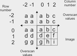
Specifies a type of overscan that processes the border pixels of a source image using overscan pixel values that replicate the border pixels. (more details...) |
‡ | a | c M10 |
g | h | i | j | k M10 |
l | m | o | p | r U27 |
t U28 |
u U36 |
v | y U75 |
aa | |||||||||||||||||||||
|
Specifies a type of overscan that processes the border pixels of a source image using transparent overscan pixel values. The overscan pixel values will be those of the ancestor buffer, and a mirror is done on the ancestor for any missing pixels. (summarize)Specifies a type of overscan that processes the border pixels of a source image using transparent overscan pixel values. (more details...) |
‡ | a | c M10 |
g | h | i | j | k M10 |
l | m | o | p | r U27 |
t U28 |
u U36 |
v | y U75 |
aa | |||||||||||||||||||||
| MIL system specific | |||||||||||||||||||||||||||||||||||||||
|
Points falling outside the source image are undefined. |
‡ | l | m | ||||||||||||||||||||||||||||||||||||
|
Sets a replacement value for the overscan pixel values. Note that to use this control type, M_OVERSCAN must be set to M_REPLACE. INQ (summarize)Sets a replacement value for the overscan pixel values. INQ (more details...) |
‡ | a | c M10 |
g | h | i | j | k M10 |
l | m | o | p | r U27 |
t U28 |
u U36 |
v | y U75 |
aa | |||||||||||||||||||||
|
Specifies the default value; the default value is 0. |
‡ | a | c M10 |
g | h | i | j | k M10 |
l | m | o | p | r U27 |
t U28 |
u U36 |
v | y U75 |
aa | |||||||||||||||||||||
|
Specifies that the overscan neighborhood pixel values will be set to the maximum value of the source buffer. |
‡ | a | c M10 |
g | h | i | j | k M10 |
l | m | o | p | r U27 |
t U28 |
u U36 |
v | y U75 |
aa | |||||||||||||||||||||
|
Specifies that the overscan neighborhood pixel values will be set to the minimum value of the source buffer. |
‡ | a | c M10 |
g | h | i | j | k M10 |
l | m | o | p | r U27 |
t U28 |
u U36 |
v | y U75 |
aa | |||||||||||||||||||||
|
Specifies the value of the overscan neighborhood pixels. |
‡ | a | c M10 |
g | h | i | j | k M10 |
l | m | o | p | r U27 |
t U28 |
u U36 |
v | y U75 |
aa | |||||||||||||||||||||
|
Sets whether to saturate the results. INQ (summarize)Sets whether to saturate the results. INQ (more details...) |
‡ | a | c M10 |
g | h | i | j | k M10 |
l | m | o | p | r U27 |
t U28 |
u U36 |
v | y U75 |
aa | |||||||||||||||||||||
|
Same as M_DISABLE. |
‡ | a | c M10 |
g | h | i | j | k M10 |
l | m | o | p | r U27 |
t U28 |
u U36 |
v | y U75 |
aa | |||||||||||||||||||||
|
Specifies not to saturate results, except when MIL can take advantage of optimization routines to accelerate the processing. In the latter case, results will be saturated and processing will be done in hardware. When it is not possible to run hardware processing optimization routines, results that overflow the buffer are undefined. (summarize)Specifies not to saturate results, except when MIL can take advantage of optimization routines to accelerate the processing. (more details...) |
‡ | a | c M10 |
g | h | i | j | k M10 |
l | m | o | p | r U27 |
t U28 |
u U36 |
v | y U75 |
aa | |||||||||||||||||||||
|
Specifies to saturate results. A result that overflows or underflows will be set to the maximum or minimum value (respectively) that can be represented in the destination buffer. If the saturation, normalization, and absolute value settings are specified for a kernel buffer, the saturation is performed after the normalization factor and the absolute value operations have been applied. (summarize)Specifies to saturate results. (more details...) |
‡ | a | c M10 |
g | h | i | j | k M10 |
l | m | o | p | r U27 |
t U28 |
u U36 |
v | y U75 |
aa | |||||||||||||||||||||
The following ControlType and corresponding ControlValue parameter settings can be specified for an M_KERNEL data buffer. These settings establish how to perform a neighborhood operation when using the specified kernel buffer.
|
For the neighborhood operation settings of M_KERNEL
data buffers
|
|||||||||||||||||||||||||||||||||||||||
|
|
Description | ||||||||||||||||||||||||||||||||||||||
| ControlValue | |||||||||||||||||||||||||||||||||||||||
|
Sets whether to take the absolute value of the results. INQ (summarize)Sets whether to take the absolute value of the results. INQ (more details...) |
|||||||||||||||||||||||||||||||||||||||
|
Same as M_DISABLE. |
|||||||||||||||||||||||||||||||||||||||
|
Specifies not to take the absolute value of the result. |
|||||||||||||||||||||||||||||||||||||||
|
Specifies to take the absolute value of the result. Note that for a structuring element buffer, you cannot take the absolute value of a result. (summarize)Specifies to take the absolute value of the result. (more details...) |
|||||||||||||||||||||||||||||||||||||||
|
Sets the normalization factor to apply to the result. Note that for a structuring element buffer, you cannot specify a normalization factor. INQ (summarize)Sets the normalization factor to apply to the result. INQ (more details...) |
|||||||||||||||||||||||||||||||||||||||
|
Specifies the default value; the default value is 1. |
|||||||||||||||||||||||||||||||||||||||
|
Specifies the normalization factor. If the factor produces an overflow in the destination, saturation might occur, depending on the M_SATURATION control type. (summarize)Specifies the normalization factor. (more details...) |
|||||||||||||||||||||||||||||||||||||||
The following ControlType and corresponding ControlValue parameter settings are used to control buffer settings that are primarily useful when working with a buffer that is a component of a container, or a buffer that will be copied to a component of a container using MbufCopyComponent().
|
For specifying settings useful with buffers that are
components
|
|||||||||||||||||||||||||||||||||||||||
| Description | |||||||||||||||||||||||||||||||||||||||
| ControlValue | |||||||||||||||||||||||||||||||||||||||
|
Sets the component type of the buffer, used when the buffer is a component of a container. The component type specifies the type of information stored in the component. INQ (summarize)Sets the component type of the buffer, used when the buffer is a component of a container. INQ (more details...) |
|||||||||||||||||||||||||||||||||||||||
|
Specifies that the component stores confidence information for the M_COMPONENT_RANGE or M_COMPONENT_DISPARITY component of the container. Coordinates associated with the confidence value 0 are considered invalid data and will not be used by 3D image processing functions. A confidence component is associated with a range or disparity component in the same container when there are no other range, disparity, or confidence components in the container. If there is more than one range, disparity, and/or confidence component in a container (for example, because a single grab into the container transmitted multiple range and confidence components), you will need to either create a child container which contains only the required components using MbufChildContainer(), or free the extra components using MbufFreeComponent(). (summarize)Specifies that the component stores confidence information for the M_COMPONENT_RANGE or M_COMPONENT_DISPARITY component of the container. (more details...) |
|||||||||||||||||||||||||||||||||||||||
|
Specifies that the component has a custom component type, identified by n, where n can be a value between 0 and 255. You can use custom component types to identify components which store information that does not fit one of the standard component types. In addition, some cameras transmit components with custom component types. Refer to your camera manual to determine what type of information is stored in these components. (summarize)Specifies that the component has a custom component type, identified by n, where n can be a value between 0 and 255. (more details...) |
|||||||||||||||||||||||||||||||||||||||
|
Specifies that the component stores a disparity map. Each pixel of a disparity map indicates the apparent distance (typically measured in pixel units) between where an object appears in the left and right images captured by a stereoscopic camera. (summarize)Specifies that the component stores a disparity map. (more details...) |
|||||||||||||||||||||||||||||||||||||||
|
Specifies that the component stores an intensity image of infrared light. |
|||||||||||||||||||||||||||||||||||||||
|
Specifies that the component stores an intensity image of visible light. |
|||||||||||||||||||||||||||||||||||||||
|
Specifies that the component stores mesh information for the M_COMPONENT_RANGE component of the container. A mesh component is associated with a range component in the same container when there are no other range or mesh components in that container. A point cloud container which has a mesh component is referred to as a meshed point cloud container. (summarize)Specifies that the component stores mesh information for the M_COMPONENT_RANGE component of the container. (more details...) |
|||||||||||||||||||||||||||||||||||||||
|
Specifies that the component stores metadata information. Metadata components are used by MIL internally. Typically, you should ignore metadata components in your application. (summarize)Specifies that the component stores metadata information. (more details...) |
|||||||||||||||||||||||||||||||||||||||
|
Specifies that the component stores an intensity image where each band represents the intensity of a specific wavelength of light. Unlike an intensity component, a multispectral component might include information about non-visible light. (summarize)Specifies that the component stores an intensity image where each band represents the intensity of a specific wavelength of light. (more details...) |
|||||||||||||||||||||||||||||||||||||||
|
Specifies that the buffer stores normals information for each point in the M_COMPONENT_RANGE component of the container. A normals component is associated with a range component in the same container when there are no other range or normals components in that container. (summarize)Specifies that the buffer stores normals information for each point in the M_COMPONENT_RANGE component of the container. (more details...) |
|||||||||||||||||||||||||||||||||||||||
|
Specifies that the component stores 3D distance/position information. The component can be either a 1-band buffer that stores a depth map, or a 3-band buffer that stores coordinates of 3D points. (summarize)Specifies that the component stores 3D distance/position information. (more details...) |
|||||||||||||||||||||||||||||||||||||||
|
Specifies that the component stores a reflectance map. Each pixel of a reflectance map indicates how much of the light hitting an object at that location is reflected back. Typically, this is an intensity image of the light wavelength used by a 3D sensor to detect 3D distance/position information. Typically, if the map was generated by a laser profiler, each line indicates the detected intensity of the laser for a single scan. (summarize)Specifies that the component stores a reflectance map. (more details...) |
|||||||||||||||||||||||||||||||||||||||
|
Specifies that the component stores a scatter map. Each pixel of a scatter map indicates how much of the light hitting an object at that location is detected scattering beneath the object's surface. (summarize)Specifies that the component stores a scatter map. (more details...) |
|||||||||||||||||||||||||||||||||||||||
|
Specifies that the component stores an intensity image of ultraviolet light. |
|||||||||||||||||||||||||||||||||||||||
|
Specifies that the component contains information of an unknown type. |
|||||||||||||||||||||||||||||||||||||||
For buffers with an M_IMAGE attribute and with M_COMPONENT_TYPE set to M_COMPONENT_RANGE or M_COMPONENT_DISPARITY, ControlType and ControlValue can also be set to one of the values below. These settings are used only when the buffer is the range or disparity component of a container passed as a source to MbufConvert3d().
A container cannot be 3D-processable or 3D-displayable unless it has a single range component with all of these settings at their default values (except for M_3D_DISTANCE_UNIT which can be any value and M_3D_REPRESENTATION, which must be set to M_CALIBRATED_XYZ or M_CALIBRATED_XYZ_UNORGANIZED).
|
For specifying settings useful with image buffers
that store 3D data and are components
|
|||||||||||||||||||||||||||||||||||||||
|
|
Description | ||||||||||||||||||||||||||||||||||||||
| ControlValue | |||||||||||||||||||||||||||||||||||||||
|
Sets which type of coordinate system to use to interpret the coordinates stored in the bands of the buffer if it is a range component. Note that MIL does not support any functionality with coordinates stored using a coordinate system type other than M_CARTESIAN. If a buffer stores information defined using another type of coordinate system, you will need to manually convert that information to cartesian coordinates before the buffer can be used with any MIL processing function. This conversion cannot be done using MbufConvert3d(). INQ (summarize)Sets which type of coordinate system to use to interpret the coordinates stored in the bands of the buffer if it is a range component. INQ (more details...) |
|||||||||||||||||||||||||||||||||||||||
|
Specifies that the buffer stores right-handed cartesian coordinates. If the buffer is a 1-band buffer, its values will be interpreted as Z-coordinates (equivalent to the pixels of a depth map). If the buffer is a 3-band buffer, the bands store the following:
This is the default value. (summarize)Specifies that the buffer stores right-handed cartesian coordinates. (more details...) |
|||||||||||||||||||||||||||||||||||||||
|
Specifies that the buffer stores cylindrical coordinates (theta-Y-rho). In a cylindrical coordinate system, points are defined relative to a reference axis and reference angle perpendicular to that axis. The Y-coordinate is the distance from the origin along the reference axis, theta (θ) is the polar angle of the point relative to a reference angle, and rho is the distance from that axis along the line described by theta and perpendicular to the reference axis (the radius). 
If the buffer is a 1-band buffer, its values store rho, the distance from a chosen reference axis. If the buffer is a 3-band buffer, the bands store the following:
Specifies that the buffer stores cylindrical coordinates (theta-Y-rho). (more details...) |
|||||||||||||||||||||||||||||||||||||||
|
Specifies that the buffer stores spherical coordinates (theta-phi-rho). In a spherical coordinate system, points are defined relative to a reference axis and a reference angle perpendicular to that axis. Rho is the distance from the origin (the radius), theta (θ) is the elevation angle of the point relative to reference axis, and phi is the azimuthal angle relative to the reference angle. 
If the buffer is a 1-band buffer, its values store rho, the distance from a chosen reference axis. If the buffer is a 3-band buffer, the bands store the following:
Specifies that the buffer stores spherical coordinates (theta-phi-rho). (more details...) |
|||||||||||||||||||||||||||||||||||||||
|
Specifies that the coordinate system type is unknown. |
|||||||||||||||||||||||||||||||||||||||
|
Sets the stereo baseline value of the stereoscopic camera used to generate the data in the buffer. This is the physical distance between the lenses of the camera. Refer to your camera manual to determine the correct value for this setting, which might differ from the true physical distance between the lenses of your camera. INQ (summarize)Sets the stereo baseline value of the stereoscopic camera used to generate the data in the buffer. INQ (more details...) |
|||||||||||||||||||||||||||||||||||||||
|
Specifies the stereo baseline value, expressed in meters. The default value is 1.0. (summarize)Specifies the stereo baseline value, expressed in meters. (more details...) |
|||||||||||||||||||||||||||||||||||||||
|
Sets the focal length of the lenses of the stereoscopic camera used to generate the data in the buffer. Refer to your camera manual to determine the correct value for this setting, which might differ from the true focal length of your camera. INQ (summarize)Sets the focal length of the lenses of the stereoscopic camera used to generate the data in the buffer. INQ (more details...) |
|||||||||||||||||||||||||||||||||||||||
|
Specifies the focal length of the lenses of the stereoscopic camera used to generate the data in the buffer if it stores a disparity map, expressed in pixels. For example, if the disparity map has 1000 pixels per millimeter of a single image sensor (after calibration), and the focal length of the lenses in millimeters is 35, the focal length in pixels is 35000. The default value is 1.0. (summarize)Specifies the focal length of the lenses of the stereoscopic camera used to generate the data in the buffer if it stores a disparity map, expressed in pixels. (more details...) |
|||||||||||||||||||||||||||||||||||||||
|
Sets the X-position of the principal point of the disparity map. This is the point in the disparity map which the optical axis of the camera intersects. INQ (summarize)Sets the X-position of the principal point of the disparity map. INQ (more details...) |
|||||||||||||||||||||||||||||||||||||||
|
Specifies X-position of the principal point, expressed in pixels. The default value is 0.0. (summarize)Specifies X-position of the principal point, expressed in pixels. (more details...) |
|||||||||||||||||||||||||||||||||||||||
|
Sets the Y-position of the principal point of the disparity map. This is the point in the disparity map which the optical axis of the camera intersects. INQ (summarize)Sets the Y-position of the principal point of the disparity map. INQ (more details...) |
|||||||||||||||||||||||||||||||||||||||
|
Specifies Y-position of the principal point, expressed in pixels. The default value is 0.0. (summarize)Specifies Y-position of the principal point, expressed in pixels. (more details...) |
|||||||||||||||||||||||||||||||||||||||
|
Sets the unit to use when the buffer is part of a container and stores natively calibrated distance data. INQ (summarize)Sets the unit to use when the buffer is part of a container and stores natively calibrated distance data. INQ (more details...) |
|||||||||||||||||||||||||||||||||||||||
|
Specifies that the distance data is provided in inches. |
|||||||||||||||||||||||||||||||||||||||
|
Specifies that the distance data is provided in millimeters. |
|||||||||||||||||||||||||||||||||||||||
|
Specifies that the distance data is provided in pixels. This setting is only useful for buffers that have the component type M_COMPONENT_DISPARITY and store a disparity map. (summarize)Specifies that the distance data is provided in pixels. (more details...) |
|||||||||||||||||||||||||||||||||||||||
|
Specifies that the distance unit is unknown. This is the default value. (summarize)Specifies that the distance unit is unknown. (more details...) |
|||||||||||||||||||||||||||||||||||||||
|
Sets whether the buffer uses a specific value to indicate invalid data. For 3-band buffers that store coordinates, the invalid data flag should be stored in the Z-axis band. Specify the value that indicates invalid data using M_3D_INVALID_DATA_VALUE. INQ (summarize)Sets whether the buffer uses a specific value to indicate invalid data. INQ (more details...) |
|||||||||||||||||||||||||||||||||||||||
|
Specifies that the buffer does not use a special value to indicate invalid data. This is the default value. (summarize)Specifies that the buffer does not use a special value to indicate invalid data. (more details...) |
|||||||||||||||||||||||||||||||||||||||
|
Specifies that the buffer uses a special value to indicate invalid data. |
|||||||||||||||||||||||||||||||||||||||
|
Sets the value used to indicate missing data when M_3D_INVALID_DATA_FLAG is set to M_TRUE. Note that this value is not used or respected by any MIL function except for MbufConvert3d() when the buffer is a component of the source container. INQ (summarize)Sets the value used to indicate missing data when M_3D_INVALID_DATA_FLAG is set to M_TRUE. INQ (more details...) |
|||||||||||||||||||||||||||||||||||||||
|
Specifies the value used to indicate missing data. The default value is 0.0. (summarize)Specifies the value used to indicate missing data. (more details...) |
|||||||||||||||||||||||||||||||||||||||
|
Sets by how much the X-coordinates stored in the buffer will be offset in the destination point cloud when the buffer is a component of a container passed as a source to MbufConvert3d(). INQ (summarize)Sets by how much the X-coordinates stored in the buffer will be offset in the destination point cloud when the buffer is a component of a container passed as a source to MbufConvert3d(). INQ (more details...) |
|||||||||||||||||||||||||||||||||||||||
|
Specifies by how much the X-coordinates stored in the buffer will be offset. The default value is 0.0. (summarize)Specifies by how much the X-coordinates stored in the buffer will be offset. (more details...) |
|||||||||||||||||||||||||||||||||||||||
|
Sets by how much the Y-coordinates stored in the buffer will be offset in the destination point cloud when the buffer is a component of a container passed as a source to MbufConvert3d(). INQ (summarize)Sets by how much the Y-coordinates stored in the buffer will be offset in the destination point cloud when the buffer is a component of a container passed as a source to MbufConvert3d(). INQ (more details...) |
|||||||||||||||||||||||||||||||||||||||
|
Specifies by how much the Y-coordinates stored in the buffer will be offset. The default value is 0.0. (summarize)Specifies by how much the Y-coordinates stored in the buffer will be offset. (more details...) |
|||||||||||||||||||||||||||||||||||||||
|
Sets by how much the Z-coordinates stored in the buffer will be offset in the destination point cloud when the buffer is a component of a container passed as a source to MbufConvert3d(). INQ (summarize)Sets by how much the Z-coordinates stored in the buffer will be offset in the destination point cloud when the buffer is a component of a container passed as a source to MbufConvert3d(). INQ (more details...) |
|||||||||||||||||||||||||||||||||||||||
|
Specifies by how much the Z-coordinates stored in the buffer will be offset. The default value is 0.0. (summarize)Specifies by how much the Z-coordinates stored in the buffer will be offset. (more details...) |
|||||||||||||||||||||||||||||||||||||||
|
Sets how 3D data is stored in the buffer; this information is used when the buffer is a range or disparity component of a container. For more information, see MbufConvert3d(). INQ (summarize)Sets how 3D data is stored in the buffer; this information is used when the buffer is a range or disparity component of a container. INQ (more details...) |
|||||||||||||||||||||||||||||||||||||||
|
Specifies that the component stores organized and natively calibrated X, Y, and Z-coordinates. This is the default value for 3-band buffers with M_SIZE_Y greater than 1. This corresponds to the GenICam Scan3dOutputMode feature set to CalibratedABC_Grid. (summarize)Specifies that the component stores organized and natively calibrated X, Y, and Z-coordinates. (more details...) |
|||||||||||||||||||||||||||||||||||||||
|
Specifies that the component stores unorganized and natively calibrated X, Y, and Z-coordinates. This is the default value for 3-band buffers with M_SIZE_Y of 1. This corresponds to the GenICam Scan3dOutputMode feature set to CalibratedABC_PointCloud. (summarize)Specifies that the component stores unorganized and natively calibrated X, Y, and Z-coordinates. (more details...) |
|||||||||||||||||||||||||||||||||||||||
|
Specifies that the component stores organized and natively calibrated X and Z-coordinates, with Y-coordinates stored in a separate array buffer. This corresponds to the GenICam Scan3dOutputMode feature set to CalibratedAC_Linescan. (summarize)Specifies that the component stores organized and natively calibrated X and Z-coordinates, with Y-coordinates stored in a separate array buffer. (more details...) |
|||||||||||||||||||||||||||||||||||||||
|
Specifies that the component stores organized and natively calibrated X and Z-coordinates, with Y-coordinates identified by the row index. This corresponds to the GenICam Scan3dOutputMode feature set to CalibratedAC. (summarize)Specifies that the component stores organized and natively calibrated X and Z-coordinates, with Y-coordinates identified by the row index. (more details...) |
|||||||||||||||||||||||||||||||||||||||
|
Specifies that the component stores organized and natively calibrated Z-coordinates, without X and Y-coordinates. This corresponds to the GenICam Scan3dOutputMode feature set to CalibratedC. (summarize)Specifies that the component stores organized and natively calibrated Z-coordinates, without X and Y-coordinates. (more details...) |
|||||||||||||||||||||||||||||||||||||||
|
Specifies that the component stores organized and natively calibrated Z-coordinates without X-coordinates; Y-coordinates are stored in a separate buffer that has an M_ARRAY attribute and is not part of the container. This corresponds to the GenICam Scan3dOutputMode feature set to CalibratedC_Linescan. (summarize)Specifies that the component stores organized and natively calibrated Z-coordinates without X-coordinates; Y-coordinates are stored in a separate buffer that has an M_ARRAY attribute and is not part of the container. (more details...) |
|||||||||||||||||||||||||||||||||||||||
|
Specifies that the component stores organized and natively calibrated Z-coordinates, with the X-coordinates identified by column index; Y-coordinates are stored in a separate buffer that has an M_ARRAY attribute and is not part of the container. This corresponds to the GenICam Scan3dOutputMode feature set to RectifiedC_Linescan. (summarize)Specifies that the component stores organized and natively calibrated Z-coordinates, with the X-coordinates identified by column index; Y-coordinates are stored in a separate buffer that has an M_ARRAY attribute and is not part of the container. (more details...) |
|||||||||||||||||||||||||||||||||||||||
|
Specifies that the component stores organized and natively calibrated Z-coordinates, with X and Y-coordinates identified by column and row index respectively. The manufacturer of your camera might refer to a range component with this setting as a depth map. This is the default value for 1-band buffers. This corresponds to the GenICam Scan3dOutputMode feature set to RectifiedC. (summarize)Specifies that the component stores organized and natively calibrated Z-coordinates, with X and Y-coordinates identified by column and row index respectively. (more details...) |
|||||||||||||||||||||||||||||||||||||||
|
Specifies that the component stores a disparity map with perspective distortion along the Y-axis. When used with MbufConvert3d(), the Y-coordinate of each point in the resulting point cloud will be generated using the row index of the corresponding pixel and compensating for perspective. This corresponds to the GenICam Scan3dOutputMode feature set to DisparityC. Typically, this setting should only be used with disparity components that have been generated using areascan cameras. (summarize)Specifies that the component stores a disparity map with perspective distortion along the Y-axis. (more details...) |
|||||||||||||||||||||||||||||||||||||||
|
Specifies that the component stores a disparity map; Y-coordinates are stored in a separate buffer that has an M_ARRAY attribute and is not part of the container. When used with MbufConvert3d(), the Y-coordinate of each point in the resulting point cloud will be taken from the specified buffer. This corresponds to the GenICam Scan3dOutputMode feature set to DisparityC_Linescan. Typically, this setting should only be used with disparity components that have been generated using linescan cameras. (summarize)Specifies that the component stores a disparity map; Y-coordinates are stored in a separate buffer that has an M_ARRAY attribute and is not part of the container. (more details...) |
|||||||||||||||||||||||||||||||||||||||
|
Specifies that the component stores a disparity map, with Y-values identified by row index. When used with MbufConvert3d(), the Y-coordinates of each point in the resulting point cloud will be generated using the row index of the corresponding pixel. Since the Y-values are uniform, no perspective correction is applied. This partially corresponds to the GenICam Scan3dOutputMode feature set to DisparityC_Linescan, except that the Y-values are not stored in a separate buffer. Typically, this setting should only be used with disparity components that have been generated using linescan cameras. (summarize)Specifies that the component stores a disparity map, with Y-values identified by row index. (more details...) |
|||||||||||||||||||||||||||||||||||||||
|
Specifies that the component stores organized and uncalibrated Z-coordinates, without X and Y-coordinates. This corresponds to the GenICam Scan3dOutputMode feature set to UncalibratedC. (summarize)Specifies that the component stores organized and uncalibrated Z-coordinates, without X and Y-coordinates. (more details...) |
|||||||||||||||||||||||||||||||||||||||
|
Sets by how much the X-coordinates stored in the buffer will be scaled in the destination point cloud when the buffer is a component of a container passed as a source to MbufConvert3d(). INQ (summarize)Sets by how much the X-coordinates stored in the buffer will be scaled in the destination point cloud when the buffer is a component of a container passed as a source to MbufConvert3d(). INQ (more details...) |
|||||||||||||||||||||||||||||||||||||||
|
Specifies by how much the X-coordinates stored in the buffer will be scaled. The default value is 1.0. (summarize)Specifies by how much the X-coordinates stored in the buffer will be scaled. (more details...) |
|||||||||||||||||||||||||||||||||||||||
|
Sets by how much the Y-coordinates stored in the buffer will be scaled in the destination point cloud when the buffer is a component of a container passed as a source to MbufConvert3d(). INQ (summarize)Sets by how much the Y-coordinates stored in the buffer will be scaled in the destination point cloud when the buffer is a component of a container passed as a source to MbufConvert3d(). INQ (more details...) |
|||||||||||||||||||||||||||||||||||||||
|
Specifies how much the Y-coordinates stored in the buffer will be scaled. The default value is 1.0. (summarize)Specifies how much the Y-coordinates stored in the buffer will be scaled. (more details...) |
|||||||||||||||||||||||||||||||||||||||
|
Sets by how much the Z-coordinates stored in the buffer will be scaled in the destination point cloud when the buffer is a component of a container passed as a source to MbufConvert3d(). INQ (summarize)Sets by how much the Z-coordinates stored in the buffer will be scaled in the destination point cloud when the buffer is a component of a container passed as a source to MbufConvert3d(). INQ (more details...) |
|||||||||||||||||||||||||||||||||||||||
|
Specifies how much the Z-coordinates stored in the buffer will be scaled. The default value is 1.0. (summarize)Specifies how much the Z-coordinates stored in the buffer will be scaled. (more details...) |
|||||||||||||||||||||||||||||||||||||||
|
Sets by how much the X-coordinates stored in the buffer will be offset in the destination point cloud from the X-coordinates in the previous row when the buffer is a component of a container passed as a source to MbufConvert3d(). INQ (summarize)Sets by how much the X-coordinates stored in the buffer will be offset in the destination point cloud from the X-coordinates in the previous row when the buffer is a component of a container passed as a source to MbufConvert3d(). INQ (more details...) |
|||||||||||||||||||||||||||||||||||||||
|
Specifies by how much the X-coordinates stored in the buffer will be offset in the destination point cloud from the X-coordinates in the previous row. The default value is 0.0. (summarize)Specifies by how much the X-coordinates stored in the buffer will be offset in the destination point cloud from the X-coordinates in the previous row. (more details...) |
|||||||||||||||||||||||||||||||||||||||
|
Sets by how much the Z-coordinates stored in the buffer will be offset in the destination point cloud from the Z-coordinates in the previous row when the buffer is a component of a container passed as a source to MbufConvert3d(). INQ (summarize)Sets by how much the Z-coordinates stored in the buffer will be offset in the destination point cloud from the Z-coordinates in the previous row when the buffer is a component of a container passed as a source to MbufConvert3d(). INQ (more details...) |
|||||||||||||||||||||||||||||||||||||||
|
Specifies by how much the Z-coordinates stored in the buffer will be offset in the destination point cloud from the Z-coordinates in the previous row. The default value is 0.0. (summarize)Specifies by how much the Z-coordinates stored in the buffer will be offset in the destination point cloud from the Z-coordinates in the previous row. (more details...) |
|||||||||||||||||||||||||||||||||||||||
|
Parameters
BufId See BufId of the main function for a description. ControlType See ControlType of the main function for a description. ControlValue See ControlValue of the main function for a description. |
|
Parameters
BufId See BufId of the main function for a description. ControlType See ControlType of the main function for a description. ControlValue See ControlValue of the main function for a description. |
| Header | Include mil.h. |
| Library | Use mil.lib. |
| DLL | Requires mil.dll. |