Calibrating your 3D reconstruction setup to create a point cloud
- See also

 Availability
 Previous
- Next

-
Allocate a camera calibration context using McalAlloc() with M_TSAI_BASED or M_3D_ROBOTICS.
-
Calibrate your camera setup using McalGrid() or McalList(). For more details, see Calibrating using calibration points from a grid and the Calibrating using calibration points from a list section of Chapter 26: Calibrating your camera setup.
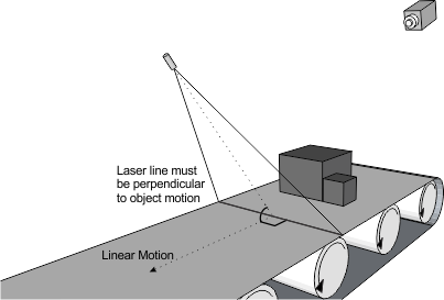
When calibrating your camera, the XY-plane (Z=0) of the absolute coordinate system must be parallel to the conveyor belt; ideally, the XY-plane lies on the same surface as the object being mapped. Note that the grid used during camera calibration might have a height itself, which can skew some calculations. In this case, specify the height (thickness) of the grid using McalGrid() with GridOffsetZ, so that the XY-plane of the absolute coordinate system is flush with the surface on which the grid is resting. For more information, see the Moving the relative coordinate system to account for height section of Chapter 31: 3D analysis using planar views of an object.
-
Use McalInquire() with the camera calibration context and M_CALIBRATION_STATUS to ensure that the camera calibration of the camera setup has been successfully performed.
-
Allocate a 3D reconstruction context using M3dmapAlloc() with M_CALIBRATED_CAMERA_LINEAR_MOTION.
-
Allocate a 3D reconstruction calibration result buffer using M3dmapAllocResult() with M_LASER_CALIBRATION_DATA.
-
Grab an image of a laser line on a planar object that has a known height. The image of a laser line on an object at a known height is called a reference plane.
-
Specify the Z-coordinate of that plane in the absolute coordinate system, using M3dmapControl() with M_CORRECTED_DEPTH. Since by default the Z-axis of the absolute coordinate system is pointing down, this value is often negative.
-
Use M3dmapAddScan() to extract the laser line information from the grabbed image and add this information to the 3D reconstruction calibration result buffer. For other methods of providing the laser line data, see the Using 3D cameras that output uncorrected depth maps section later in this chapter.
If, after calling M3dmapAddScan(), but before calling M3dmapCalibrate(), you need to discard the last scan added (for example, as the result of a diagnosis using M3dmapDraw() with M_DRAW_PEAKS_LAST), it is possible to do so by calling M3dmapClear() with M_REMOVE_LAST_SCAN.
-
Repeat steps 3 to 5 for every reference plane that you want to use to calibrate your 3D reconstruction setup. If you are calibrating for a vertical laser plane (parallel to the XZ-plane), only one reference plane is required. If the laser plane is not vertical, as shown below, you must provide a minimum of 2 reference planes.
However, even if you are using a vertical laser plane, your results will be more accurate if you calibrate using more plane heights. Note that you can use the surface on which the object is resting as a reference plane.
The size and depth of the source image buffer containing the laser lines must not change when making multiple calls to M3dmapAddScan(), and you must use the same destination result buffer.
-
Call M3dmapCalibrate() with the 3D reconstruction context, calibration result buffer, and camera calibration context.
-
Use M3dmapInquire() with M_CALIBRATION_STATUS, while specifying the 3D reconstruction context, to ensure that the calibration of the 3D reconstruction setup has been successfully performed.
-
Free the 3D reconstruction calibration result buffer using M3dmapFree().
After ensuring that your 3D reconstruction setup meets the requirements described in the Configuring the laser line profiling setup section earlier in this chapter, you must calibrate the 3D reconstruction setup. The objective of 3D reconstruction calibration is to establish the relationship between the laser line's displacement when over an object and the real-world depth of the object. Calibrating your 3D reconstruction setup is mandatory before generating point clouds or partially corrected depth maps using the 3D Reconstruction module.
3D reconstruction calibration requires a specific type of 3D reconstruction result buffer, allocated using M3dmapAllocResult() with M_LASER_CALIBRATION_DATA.
Note that there are slight differences when calibrating the 3D reconstruction context for a partial depth map. These differences are explained in the Partially corrected depth maps section later in this chapter.
Calibrating to create a point cloud
To create a point cloud, you must first perform two different calibrations: a camera calibration and a 3D reconstruction setup calibration.
To calibrate a camera intended for a 3D reconstruction setup:
Once your camera is calibrated, you must calibrate the 3D reconstruction setup. To do so:
The following code snippet is an example of the steps required to calibrate in M_CALIBRATED_CAMERA_LINEAR_MOTION 3D reconstruction mode, in the case of a vertical laser plane setup (which requires only one reference plane).
/* Allocate 3dmap objects. */
M3dmapAlloc(MilSystemId, M_LASER, M_CALIBRATED_CAMERA_LINEAR_MOTION, &LaserId);
M3dmapAllocResult(MilSystemId, M_LASER_CALIBRATION_DATA, M_DEFAULT, &ScanId);

/* Inquire internal locate peak Mim context Id, if peak detection needs configuration. */
M3dmapInquire(LaserId, M_DEFAULT, M_LOCATE_PEAK_1D_CONTEXT_ID, &MilPeakLocatorId);

/* Set settings with M3dmapControl() and MimControl(), if needed. */
/* ... */

/* Get image of laser line on Z=0 reference plane.  */
/* MbufLoad can also be used to load an image.      */
MdigGrab(DigId, MilImageId);

/* Calibrate 3D reconstruction context. */
/* MilCalibrationId is the identifier of the calibration context calibrated by
   McalGrid() or McalList() in a 3D mode. */
M3dmapAddScan(LaserId, ScanId, MilImageId, M_NULL, M_NULL, M_DEFAULT, M_DEFAULT);
M3dmapCalibrate(LaserId, ScanId, MilCalibrationId, M_DEFAULT);
When you are set up to create a point cloud (M3dmapAlloc() with M_CALIBRATED_CAMERA_LINEAR_MOTION), calibrating your 3D reconstruction setup also defines the laser line coordinate system, a real-world coordinate system with its X-axis on the intersection between the laser plane and the conveyor belt, and its Y-axis along the path of the conveyor's movement. Initially, the relative coordinate system of the 3D reconstruction result buffer has the same pose as the laser line coordinate system. The relative coordinate system is used to return all 3D points generated by the 3D Reconstruction module. For more information, see the Understanding the laser line coordinate system subsection of the 3D coordinate systems and the coordinates of a point cloud section later in this chapter.
Inspecting laser line calibration
After calibrating an M_CALIBRATED_CAMERA_LINEAR_MOTION 3D reconstruction context, it is possible to see how the laser lines detected at 3D reconstruction calibration were mathematically altered to best fit the equation of the laser plane; to do so, use M3dmapDraw() with M_DRAW_CALIBRATION_LINES and the 3D reconstruction context.
You can draw all the extracted laser lines used to calibrate the 3D reconstruction context, using M3dmapDraw() with M_DRAW_CALIBRATION_PEAKS.
You can inquire the root mean squared error of the fit, using M3dmapInquire() with M_FIT_RMS_ERROR.
Specifying offsets when the 3D reconstruction calibration image is a subset of the grabbed image
When calibrating the 3D reconstruction setup, and you have an M_CALIBRATED_CAMERA_LINEAR_MOTION 3D reconstruction context, it is important to note whether you are using a subset of the entire grabbed image during the runtime application. The subset of the grabbed image, whether through source offsets (MdigControl() with M_SOURCE_OFFSET_... and M_SOURCE_SIZE_...) or child buffers (MbufChild2d()), must be the same during 3D Reconstruction calibration as it is during the runtime application.
If you are supplying a subset of the grabbed image, whether through source offsets or child buffers, to M3dmapAddScan(), the origin of the image buffer passed to McalGrid() must correspond to the origin of the image buffer passed to M3dmapAddScan(). If these two points do not correspond to the same real-world coordinate, you must specify the offset(s) of the image buffer used during 3D reconstruction calibration, before calling M3dmapAddScan() with M_LASER_CALIBRATION_DATA for the first time. Specify the offsets using M3dmapControl() with M_EXTRACTION_CHILD_OFFSET_X and M_EXTRACTION_CHILD_OFFSET_Y.

In the case where the image buffer used in camera calibration is a subset of the entire grabbed image, and the image buffer used in 3D reconstruction calibration is a subset of the subset, you must specify the offset with respect to the subset used for camera calibration.
