Features
- See also

 Availability
 Previous
- Next

-
Explicitly specify the shape and size of the region. This is referred to as an explicitly-defined metrology region. Most applications typically use this type of region.
-
Set the region's shape and size using a graphic in a 2D graphics list. This is referred to as a 2D graphics list metrology region.
When using a 2D graphics list metrology region, you must specify the geometry (shape) of the region with MmetSetRegion(), and then add M_FROM_GRAPHIC_LIST; for example, M_ARC + M_FROM_GRAPHIC_LIST. In this case, you must add the corresponding graphic to the 2D graphics list using an appropriate Mgra...() function; for example, when using an M_ARC metrology region, you can call MgraArc() to add an arc to the 2D graphics list. The 2D graphics list must contain only one graphic and it must have the same geometric-shape as specified with MmetSetRegion(). The advantage of defining a 2D graphics list metrology region is that you can set it with respect to the relative coordinate system as well as set it interactively.
-
Define the metrology region based on other features by passing a derived metrology region object to MmetSetRegion(). This is referred to as a derived metrology region.
When using a derived metrology region (MmetSetRegion() with M_FROM_DERIVED_GEOMETRY_REGION), you must allocate a derived metrology region object using MmetAlloc() with M_DERIVED_GEOMETRY_REGION, and then set it up using MmetControl() with M_REGION_.... Once you specify the geometry of the derived metrology region using the M_REGION_GEOMETRY control type, you can set most of the geometry's attributes either explicitly or derive them based on a feature. Use the corresponding M_REGION_..._TYPE control type to specify which. For example, instead of specifying explicit X- and Y-coordinates to set the position of a rectangular metrology region, you can derive its position according to the position of a point feature.
-
Mathematically defined (M_PARAMETRIC).
-
Geometrically derived from a set of other features (all build operations except M_PARAMETRIC). The features used to build a constructed feature are referred to as base features.
Once you have allocated your metrology context using MmetAlloc(), you must then add features to the metrology template, using MmetAddFeature(). You can add both physically measured and constructed features.
The following table lists all available features, their definition, and whether they can be physically measured or constructed.
|
Feature |
Definition |
Physically measured |
Constructed |
|
Arc |
A continuous portion of a circle. |
Yes |
Yes |
|
Circle |
A closed curve of points where each point is located at the same distance from one center point. |
Yes |
Yes |
|
Edgel |
Elementary points (or edge elements) within an edge. Each edgel represents an X- and Y-position, and the angular direction of the gradient. |
Yes |
Yes |
|
Line |
A one-dimensional geometric primitive that is straight and infinitely long. |
— |
Yes |
|
Local frame |
A constructed reference frame. |
— |
Yes |
|
Point |
A geometric primitive that represents an X- and Y-position. |
Yes |
Yes |
|
Segment |
Part of a geometric line that is defined by a start point and end point. |
Yes |
Yes |
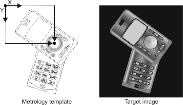
If you associate a camera calibration context to the target image, you must use real-world units to define or position features in the template. If there is no camera calibration context, use pixel units. For more information, see the Camera calibration - overview section of Chapter 26: Calibrating your camera setup.
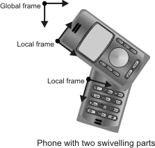
Reference frame
All positional information in a metrology template, for physically measured features (including their metrology region) and constructed features, is relative to a coordinate system. The coordinate system that you use as your reference is called the reference frame.
Every feature and metrology region has a reference frame with which it is associated. The reference frame can either be the global frame (created by default) or a local frame (user-defined feature).
You can reposition, rotate, or change reference frames, which can be useful when dealing with multiple parts in the same image.
To reposition or rotate a reference frame, use MmetControl() with M_POSITION_X, M_POSITION_Y, and M_ANGLE. To change a feature's reference frame, use MmetControl() with M_FEATURE_INDEX() or M_FEATURE_LABEL() to specify the feature and M_REFERENCE_FRAME to set the label or index of its new reference frame.
If you change a reference frame, move a reference frame, or alter its angle, all features and metrology regions associated with that reference frame are modified accordingly.
Global frame
By default, a feature's reference frame is set to the global frame. When you allocate a metrology context, MIL automatically creates the global frame, assigns it an index of 0, and labels it M_GLOBAL_FRAME. The global frame is the first coordinate system used to define the features to add to the metrology template of a metrology context. The global frame always exists and you cannot delete it. If the target image is not calibrated, the global frame's default origin (0,0) is aligned with the center of the top-left corner pixel of the target image. If the target image is calibrated, the global frame's default origin is aligned with the origin of the relative (world) coordinate system. To move the global frame, use MmetSetPosition().
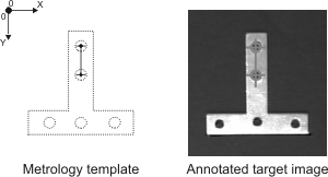
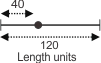
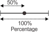
In the following example, the position (center) of a ring-shaped metrology region is set according to the global frame.
Local frame
In addition to the default reference frame (global frame), you can add your own reference frame feature anywhere within the global frame. Each reference frame you add is called a local frame.
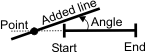
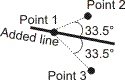
To add a local frame, use MmetAddFeature() with M_LOCAL_FRAME. You can add a local frame by cloning it from another local frame (M_CLONE_FEATURE), constructing it from two points or one point and an angle (M_CONSTRUCTION), or by providing specific position and angle values (M_PARAMETRIC).
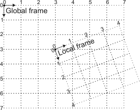
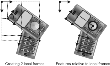
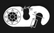
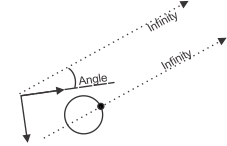
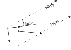
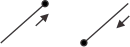
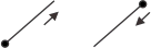
The following example illustrates the use of three reference frames: the global frame, a local frame constructed with position and angle values, and a local frame constructed with two points. The first illustration shows how the local frames are created. The second illustration shows how features can be added (a circle and a segment) according to each local frame. This is useful since the two parts of the phone swivel, though they are independently stable.
Set position
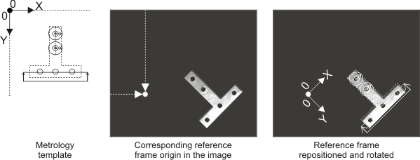
When you are setting the position of a reference frame within the metrology template, you are typically assuming that the corresponding position in the target image is at the same location. However, in real-world applications, the location of this position within the target image does not always correspond to the position in the template.
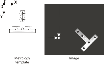
To help solve this problem, you can change the position of your reference frame just before performing metrology calculations.
To change the position of your reference frame, use MmetSetPosition() with explicit positional values (M_POSITION), translation and rotation values (M_GEOMETRIC), transformation coefficients (M_FORWARD_COEFFICIENTS), or the results of another MIL module (M_RESULT).
For example, you can use the MIL Model Finder module to find the object, and then use that occurrence's found position to place the reference frame with which to perform metrology calculations. For more information on an occurrence's found position, see the Reference axis subsection of the Customizing search settings section of Chapter 8: Geometric Model Finder.
Positions set with MmetSetPosition() are not saved with the metrology context. Note that you are not limited to repositioning the reference frame; you can move the expected location of any physically measured or parametrically constructed feature. To do so, use MmetSetPosition() and specify the label or index of the feature. Moving a feature other than the reference frame is typically useful only for very advanced applications.
(Physically) measured features
A physically measured feature is a geometric primitive (segment, arc, circle, point, and edgel) that can be physically measured within a specified metrology region in the target image. To add a physically measured feature to the template, use MmetAddFeature() with M_MEASURED.
All physically measured features are composed of edgels (edge elements). A physically measured segment, arc, circle, and point feature contains edgels that form its definitive geometric shape; conversely, an edgel feature is a group of edgels without a definitive geometry. For more information, see the (Physically measured) edgel features subsection of this section.
Metrology regions
A metrology region is an area in the target image that contains the edgels MIL uses to establish the physically measured feature. By default, MIL uses the entire target image as the metrology region of the measured feature. However, to reduce the likelihood of getting unwanted features, and to speed up the calculation, you should typically restrict this area, using MmetSetRegion().
For example, you can specify that the physically measured feature must not only be within the specified target image, but that it must also be within the specified ring, arc, segment, or rectangle metrology region. In general, good results come from well-defined metrology regions. Note that the features with which to build constructed features can also have a delimited metrology region.
When you call MmetSetRegion(), you can define the metrology region in one of the following ways.
Regardless of how you define the metrology region, the regions themselves behave similarly; that is, they restrict the area in the target image from which to establish your physically measured features.
By default, when the target image is calibrated, the metrology region closely follows the image distortion. You can disable high accuracy for the metrology region of a feature and have the Metrology module approximate the distortion using MmetControl() with M_REGION_ACCURACY_HIGH set to M_DISABLE. This results in a quicker processing time.
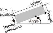
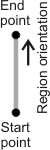
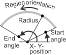
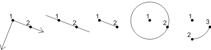
Each metrology region has an orientation, which refers to the alignment of a metrology region, with respect to a reference frame. The following example shows 4 metrology regions (ring, arc, segment, and rectangle) and their orientation, as depicted with an arrow. You can draw a metrology region (and its orientation) using MmetDraw() with M_DRAW_REGION. Note that for circular metrology regions (arc, ring, ring-sector), the metrology region's orientation is radial.
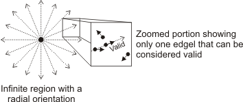
For the features to be extracted, they must not only fall within the metrology region, but their edgels' gradient angle must also fall along the region's orientation. Various control types can be used to set a valid relationship between the metrology region's orientation, and the edgels' gradient angle. For more information, see the Gradient angle subsection of the Degrees of freedom section later in this chapter.
The metrology region's position is set relative to the global frame by default. You can, however, use the coordinate system of any reference frame.
The following table lists all available metrology regions, and the physically measured features that can be extracted from them.
|
Metrology region |
Feature |
|||||
|
Arc |
Circle |
Edgel |
Point |
Segment |
||
|
Arc |
— |
— |
— |
Yes |
— |
|
|
Infinite (default) |
Yes |
Yes |
Yes |
Yes |
Yes |
|
|
Rectangle |
— |
— |
Yes |
— |
Yes |
|
|
Ring |
— |
Yes |
Yes |
— |
— |
|
|
Ring-sector |
Yes |
— |
Yes |
— |
Yes |
|
|
Segment |
— |
— |
— |
Yes |
— |
|
For an infinite metrology region (M_INFINITE), you must set the X- Y-position of the origin of the region. You must also explicitly set the angle of orientation (the default is the same as the reference frame). For a rectangular metrology region (M_RECTANGLE), you must set the X- Y-position of the origin of the region. You must also set the region's width, height, and angle. The orientation is determined by the origin's position and angle. For a segment-shaped metrology region (M_SEGMENT), you must set the X- Y-position of the segment's start point and end point. The orientation is from start point to end point. For an arc-shaped metrology region (M_ARC), you must set the X- Y-position of the origin of the region. You must also set the region's radius, start angle and end angle. The orientation is from start angle to end angle.
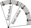
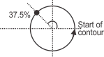
For a ring-shaped metrology region (M_RING), you must set the X- Y-position of the origin (center) of the region. You must also set the start radius and the end radius. To delimit only a sector of a ring (M_RING_SECTOR), you must set the start angle and end angle of the ring. The orientation is from the start radius to the end radius. Also, the region itself is set counter-clockwise, from the start angle to the end angle (for ring-sector).
Note that M_INFINITE is similar to M_RECTANGLE, however an infinite metrology region does not have a width and a height (boundaries).
The following examples illustrate rectangle, segment, arc, and ring-sector metrology regions.
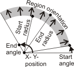
Note that, for ring-shaped metrology regions, switching the start radius and end radius reverses the orientation.
Unlike other physically measured features, multiple measured points can be extracted from the metrology region. For more information, see the Multiple features subsection of this section.
Best fit, inner fit, and outer fit operations
To add a physically measured feature, you must typically set its fit operation. The fit operation (for example, a best fit operation) establishes the feature (for example, a physically measured circle feature) by processing its active edgels, which refer to those edgels, in the metrology region, that satisfy the edgel constraints (MmetControl() with M_EDGEL_ANGLE_RANGE, M_EDGEL_RELATIVE_ANGLE, and M_EDGEL_SELECTION_RANK). The active edgels that the fit operation actually uses are referred to as the fitted edgels. For more information, see the Active edgels and fitted edgels subsection of the Degrees of freedom section later in this chapter.
The following table lists the fit operations and the features you can build with them.
|
Build operation |
Feature to build |
||||
|
Arc |
Circle |
Edgel |
Point |
Segment |
|
|
Best fit (default) |
Yes |
Yes |
— |
Yes |
Yes |
|
Inner fit |
— |
Yes |
— |
— |
Yes |
|
Outer fit |
— |
Yes |
— |
— |
Yes |
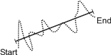
A feature built with the best fit operation (M_FIT) will pass as close to as many of the active edgels as possible. Note that the best fit segment separates the inner and outer fit regions, which are used to calculate the inner and outer fit segments. A feature built with the best fit operation (M_STANDARD_FIT) gives more importance to the edgels whose gradient's orientation follows the region's orientation. The starting point of the best fit segment is the extremity closest to the origin of the reference frame. By default, when specifying an M_FIT operation, MIL performs a standard best fit. However, when dealing with a lot of outliers (outlier pixels/points), you can change this to a robust best fit, by calling MmetControl() with M_FIT_TYPE set to M_ROBUST_FIT.
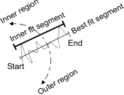
A feature built with the inner fit operation (M_INNER_FIT) will represent the innermost boundary of the set of the active edgels. For a circle feature, the inner fit is the largest possible circle that contains none of the active edgels. For a segment feature, the inner fit depends on the best fit segment. The active edgels used to build the inner fit segment are on the counter-clockwise side of the best fit segment, relative to its direction. The inner fit segment passes through the two farthest active edgels of the inner fit region such that all the active edgels of the inner fit region are located on the same side of the inner fit segment.
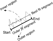
A feature built with the outer fit operation (M_OUTER_FIT) will represent the outermost boundary of the set of active edgels. For a circle feature, the outer fit is the smallest possible circle that contains all of the active edgels. For a segment feature, the outer fit depends on the best fit segment. The active edgels used to build the outer fit segment are on the clockwise side of the best fit segment, relative to its direction. The outer fit segment passes through the two farthest active edgels of the outer fit region such that all the active edgels of the outer fit region are located on the same side of the outer fit segment.
The following table illustrates an arc, circle, and segment feature added with the different fit operations; the operations are performed on the active edgels provided.
|
Build operation |
Feature to build |
||
|
Arc |
Circle |
Segment |
|
|
Best fit |

|

|
|
|
Inner fit |
Not available |

|
|
|
Outer fit |
Not available |

|
|
When using a fit operation, you can fine-tune the fit process by calling MmetControl() and specifying fit constraints; for example, for greater precision, you can increase the maximum number of fit iterations that MIL can use to establish the feature (M_FIT_ITERATIONS_MAX). Such fit constraints can alter the precision of the edge that is ultimately fit; however, they might not reliably discard outliers (outlier pixels/points) when they significantly impact the initial fit (the first iteration of the fit). When dealing with a lot of outliers, use a robust best fit (M_ROBUST_FIT). For more information on fit constraints, see the Active edgels and fitted edgels subsection of the Degrees of freedom section later in this chapter.
Note that features built with a fit operation will not necessarily touch the active edgels on which it is based. Also, to determine the length of a segment feature built using a fit operation, MIL projects the fitted edgels in the feature's metrology region onto the segment.
(Physically measured) edgel features
Edgel features do not have a definitive geometry; they are built using the raw information (edgels) extracted from the metrology region. Each edgel represents an X- and Y-position, and an angular direction (of the gradient). An edgel feature typically contains numerous edgels.
To add an edgel feature, use MmetAddFeature() with M_MEASURED and M_EDGEL. By default, edgel features are built using all the edgels in the feature's metrology region. However, you can choose to eliminate unwanted edgels, based on their gradient angle; this can prove useful since it allows you to customize the extracted edgels to fit your needs. For more information, see the Gradient angle subsection of the Degrees of freedom section later in this chapter.
An edgel feature is useful to add an atypical shape to the metrology template. That is, you can add features that do not represent a geometric primitive, such as an arc, circle, point, or segment.

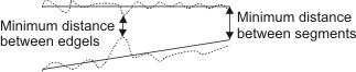
The edgel information of a feature might also prove useful in several types of advanced applications. For example, you might want to set a true minimum distance tolerance between the edgels that compose two segments, rather than having the minimum distance based on the fitted segments that are built from the edgels.
Constructed features
A constructed feature is a geometric primitive (point, arc, circle, segment, line, edgel, and local frame) that is either:
To add a constructed feature, use MmetAddFeature() with M_CONSTRUCTED. For constructed features that are geometrically derived, you must also specify the label of the feature(s) to use for construction. These features can be referred to as base features.
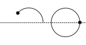
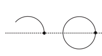
The following example shows a constructed segment added from the constructed center points of 2 physically measured circles.
To add a constructed feature, you must set the operation with which to build the feature. For a constructed feature that is geometrically derived, the operation selects how to use the specified base feature(s) to build the constructed feature.
The following table lists all constructed features, and the operations to build them.
|
Build operation |
Feature to build |
||||||
|
Arc |
Circle |
Edgel |
Line |
Local frame |
Point |
Segment |
|
|
Absolute angle |
— |
— |
— |
— |
— |
Yes |
— |
|
Absolute position |
— |
— |
— |
— |
— |
Yes |
— |
|
Angle |
— |
— |
— |
Yes |
— |
— |
— |
|
Basic construction |
Yes |
Yes |
— |
Yes |
Yes |
— |
Yes |
|
Best fit |
Yes |
Yes |
— |
Yes |
— |
— |
Yes |
|
Bisector |
— |
— |
— |
Yes |
— |
— |
— |
|
Center |
— |
— |
— |
— |
— |
Yes |
— |
|
Clone |
Yes |
Yes |
Yes |
Yes |
Yes |
Yes |
Yes |
|
Closest |
— |
— |
— |
— |
— |
Yes |
— |
|
Closest to infinity point |
— |
— |
— |
— |
— |
Yes |
— |
|
Copy feature edgels |
— |
— |
Yes |
— |
— |
— |
— |
|
End position |
— |
— |
— |
— |
— |
Yes |
— |
|
Extended intersection |
— |
— |
— |
— |
— |
Yes |
— |
|
External feature |
— |
— |
Yes |
— |
— |
— |
— |
|
Group edgels (default) |
— |
— |
Yes |
— |
— |
— |
— |
|
Inner fit |
— |
Yes |
— |
— |
— |
— |
Yes |
|
Intersection |
— |
— |
— |
— |
— |
Yes |
— |
|
Max distance point |
— |
— |
— |
— |
— |
Yes |
— |
|
Max of min distance point |
— |
— |
— |
— |
— |
Yes |
— |
|
Middle |
— |
— |
— |
— |
— |
Yes |
— |
|
Outer fit |
— |
Yes |
— |
— |
— |
— |
Yes |
|
Parallel |
— |
— |
— |
Yes |
— |
— |
— |
|
Parametric (default) |
Yes |
Yes |
— |
Yes |
Yes |
Yes |
Yes |
|
Perpendicular |
— |
— |
— |
Yes |
— |
— |
— |
|
Relative angle |
— |
— |
— |
— |
— |
Yes |
— |
|
Relative position |
— |
— |
— |
— |
— |
Yes |
— |
|
Relative sector |
— |
— |
— |
Yes |
— |
— |
— |
|
Start position |
— |
— |
— |
— |
— |
Yes |
— |
Using metrology regions with constructed features
The base features of constructed features built using a fit operation can be delimited by a metrology region. You must call MmetSetRegion() to specify the metrology region for each base feature. The base feature of a constructed edgel feature built using a clone operation can also be delimited by a metrology region. MIL only uses the edgels or points within the delimited region of the base feature to build the constructed feature; edgels or points outside the region are clipped.
Metrology regions for the base features of constructed features are the same as metrology regions for physically measured features. For more information, the Metrology regions subsection of this section.
Basic construction (using points)
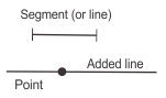
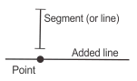
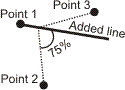
The basic construction operation, M_CONSTRUCTION, creates a constructed feature based on points, which are considered a feature's most fundamental (basic) elements. The number of points MIL requires, and how MIL implements them, are dependent on the feature you are constructing. The following example shows how a local frame, line, segment, circle, and arc are built using 2 or 3 points.
When using M_CONSTRUCTION, you can specify the following features with which to build the new feature: points, circles, arcs, or local frames. If you specify a non-point feature, MIL uses that feature's most significant point; that is, for a circle or arc, MIL takes its center point, and for a local frame, MIL takes its origin point.
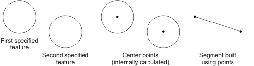
In the following example, a segment (M_CONSTRUCTED with M_SEGMENT) is built using M_CONSTRUCTION with two specified circle features (FeatureLabelArrayPtr).
Cloning and copying
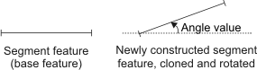
The clone operation, M_CLONE_FEATURE, creates a constructed feature that is an exact duplicate, or modified replica, of the specified base feature, which can be constructed or physically measured. The clone operation is available for building any constructed feature. The base feature of a constructed edgel feature built using a clone operation can be delimited by a metrology region.
Metrology allows you to modify certain aspects of a cloned feature, using MmetControl() with M_CLONE_.... For example, you can translate (M_CLONE_OFFSET_X, M_CLONE_OFFSET_Y), rotate (M_CLONE_ANGLE), and/or scale (M_CLONE_SCALE) a cloned feature.
When modifying a cloned feature, values (position, scale, and angle) are relative to the reference frame of the clone's base feature. When cloning a reference frame, its associated features are not cloned.
For constructed edgel features only, you can also use the operation M_COPY_FEATURE_EDGELS. This creates a new constructed edgel feature that contains the edgels of the specified base features, each of which can be physically measured or a constructed edgel feature.
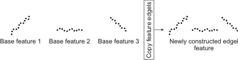
By default, the M_COPY_FEATURE_EDGELS operation copies all the edgels of the base features to the newly constructed edgel feature. However, for physically measured base features, you can restrict the operation to copy only the active edgels or only the fitted edgels of the base features. For constructed edgel base features, MIL considers the edgels active (not fitted). For more information, see the Copy feature edgels subsection of the Degrees of freedom section later in this chapter.
Fit
The fit operations create a constructed feature that is the best fit (M_FIT), inner fit (M_INNER_FIT), or outer fit (M_OUTER_FIT), of the feature information (base features) that you provide. This information can be points and/or edgels; the added feature will not necessarily touch these points/edgels. For example, you can add a constructed segment that is built using the best fit of a physically measured point feature (which contains multiple physically measured points). In this case, the constructed segment will pass as close to as many of the points as possible. When dealing with a lot of outliers (outlier pixels/points), try using a robust best fit, by calling MmetControl() with M_FIT_TYPE set to M_ROBUST_FIT. The base features of a constructed feature built using a fit operation can be delimited by a metrology region.
In general, fit operations for constructed features and physically measured features behave similarly. For more information, see the Best fit, inner fit, and outer fit operations subsection of this section.
Operations for building point features
A point feature can be constructed using one of several specialized operations. For example, you can use the center operation (M_CENTER) to construct a point at the center of a segment. The following table illustrates some of the operations available to build a point based on the specified feature(s).
|
Build operation |
Feature(s) used to build the point |
||
|
Circle or Arc |
Segment |
Several features |
|
|
Absolute angle |
|
Not available |
Not available |
|
Absolute position |
|
|
Not available |
|
Center |
|

|

|
|
Closest |
Not available |
Not available |

|
|
Closest to infinity point |
|
|
Not available |
|
Extended intersection |
Not available |
Not available |

|
|
Intersection |
Not available |
Not available |

|
|
Max distance point |
Not available |
Not available |

|
|
Max of min distance point |
Not available |
Not available |

|
|
Middle |
|

|
Not available |
|
Position end |
|
|
Not available |
|
Position start |
|
|
Not available |
|
Relative angle |
|
Not available |
Not available |
|
Relative position |

|
|
Not available |
Operations for building line features
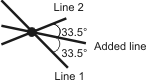
A line feature can be constructed using one of several specialized operations. For example, you can use the parallel operation (M_PARALLEL) to construct a line parallel to a specified segment.
The following table illustrates some of the operations available to build a line based on the specified feature(s). Some operations also require an angle value.
|
Build operation |
Feature(s) used to build the line |
||
|
A segment and a point |
Three points |
Two lines |
|
|
Angle |
|
Not available |
Not available |
|
Bisector |
Not available |
|
|
|
Parallel |
|
Not available |
Not available |
|
Perpendicular |
|
Not available |
Not available |
|
Relative sector |
Not available |
|
Not available |
Parametrically constructed features
Most constructed features can be built mathematically (M_PARAMETRIC) by specifying explicit values, such as the feature's position and angle. You must use MmetControl() to specify the required values needed for the construction.
For example, to build a line parametrically, you must use MmetControl() with M_LINE_A, M_LINE_B, and M_LINE_C to specify the coefficients A, B, and C of the line equation ( A x + B y + C = 0).
Note that since a line is infinitely long, it has no position.
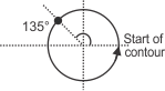
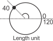
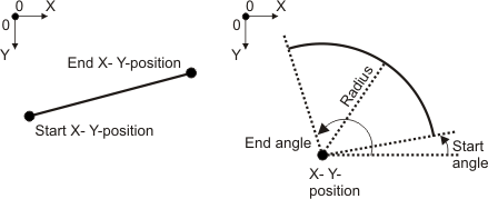
The following illustration shows how a segment and arc are constructed by providing explicit positional values. For an arc, you must also provide its radius, start angle, and end angle.
Multiple features
A multiple feature is a feature that holds several instances of that same feature type; every instance of the feature type is considered a subfeature of the multiple feature. For example, a point feature can be a collection of several physically measured points, each of which is a subfeature (subpoint) of the point feature. Point and edgel features are considered multiple features. In certain cases, you can access subpoints; however, you can never access subedgels.
A multiple point feature is created when the metrology region associated with a point feature contains more than one edgel. The subfeatures are numbered in ascending order along the orientation of the metrology region.
You might need to specify the individual subfeatures (points) to use when adding a constructed feature based on a subfeature of a multiple physically measured point feature. To do so, use the FeatureLabelArrayPtr parameter to specify the label of the multiple point feature, and use the SubFeatureIndexArrayPtr parameter to specify the indices of the subpoints. The following table shows how a feature can be added using 8 points (specified from 5 features).
|
FeatureLabelArrayPtr |
SubFeatureIndexArrayPtr |
|
MultiplePointFeature1 |
19 |
|
MultiplePointFeature2 |
1 |
|
MultiplePointFeature2 |
13 |
|
MultiplePointFeature3 |
1 |
|
MultiplePointFeature3 |
14 |
|
MultiplePointFeature3 |
20 |
|
MultiplePointFeature4 |
8 |
|
MultiplePointFeature5 |
1 |